


23
Sundance Technology ST201 PRELIMINARY draft 2
3. Set MgmtClk
4. Write the desired data bit to MgmtData
5. Wait a minimum of 200 ns
To perform a Z cycle used during the Turnaround
portion of a register read frame, the host system
should follow the procedure below.
1. Clear MgmtClk
2. Wait a minimum of 200 ns
3. Set MgmtClk
4. Clear MgmtDir
5. Wait a minimum of 200 ns
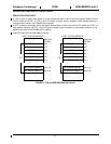
Using the read, write, and Z cycle procedures, a
Read management frame is executed as follows.
1. Set MgmtDir.
2. Execute 32 write cycles to transmit the 32 bit
Preamble of 0xffffffff.
3. Execute 2 write cycles to transmit the 2 bit
Start of Frame of 0x01.
4. Execute 2 write cycles to transmit the 2 bit
Operation Code of 0x02.
5. Execute 5 write cycles to transmit the 5 bit
PHY Address to identify the target PHY device
for the Read frame.
6. Execute 5 write cycles to transmit the 5 bit
Register Address to identify the register to be
read within the PHY device.
7. Execute a Z cycle to prepare the interface to
receive read data bits (first half of Read Turn-
around).
8. Execute a single read cycle (second half of
Read Turnaround). The bit read from the PHY
will be a zero if the PHY intends to respond to
the Read frame. A value of one indicates that
no PHY device is responding, and the data to
follow is invalid.
9. Execute 16 read cycles to read the data from
the PHY register. Data bits are read starting
with register bit 15 and ending with register bit
0.
10. Execute a Z cycle to terminate the frame.
Using the read, write, and Z cycle procedures, a
Write management frame is executed as follows.
1. Set MgmtDir.
2. Execute 32 write cycles to transmit the 32 bit
Preamble of 0xffffffff.
3. Execute 2 write cycles to transmit the 2 bit
Start of Frame of 0x01.
4. Execute 2 write cycles to transmit the 2 bit
Operation Code of 0x01.
5. Execute 5 write cycles to transmit the 5 bit
PHY Address to identify the target PHY device
for the Write frame.
6. Execute 5 write cycles to transmit the 5 bit
Register Address to identify the register to be
written within the PHY device.
7. Execute 2 write cycles to transmit the 2 bit
Write Turnaround value of 0x02.
8. Execute 16 write cycles to write the data to the
PHY register. Data bits are written starting with
register bit 15 and ending with register bit 0.
9. Execute a Z cycle to terminate the frame.
EEPROM COMMANDS
The EepromCtrl register provides the host with a
method for issuing commands to the ST201’s
serial EEPROM controller. Individual 16-bit word
locations within the EEPROM may be written, read
or erased. Also, the EEPROM’s WriteEnable, Writ-
eDisable, EraseAll and WriteAll commands can be
issued.
Two-bit opcodes and 8-bit addresses are written to
the EepromCtrl register to cause the ST201 to
carry out the desired EEPROM command. If data is
to be written to the EEPROM, the 16-bit data word
must be written to EepromData by the host system
prior to issuing the associated write command.
Similarly, if data is to be read from the EEPROM,
the read data will be available via EepromData reg-
ister after issuing the associated read command.
A mechanism within the EEPROM interface auto-
matically disables writes and erasures to prevent
accidental data changes should power be inter-
rupted. The ST201 disables writes and erasures
after every write or erase type command has been
executed. To write or erase a series of locations,
the host must issue the WriteEnable command
prior to every write or erase type command.
The serial EEPROM can only clear bits to zero dur-
ing a write command and cannot set individual bits
to ones. Therefore, an Erase or EraseAll command
must be issued prior to attempting to write data to
the EEPROM.
The EEPROM is a particularly slow device. It is
important that the host wait until the EepromBusy
bit is false before issuing a command to EepromC-
trl.
The procedure for a typical write operation to the
EEPROM is as follows:
1. Verify EepromBusy is false.
2. Issue the WriteEnable command
(opcode = 00 11xx xxxx)
3. Verify EepromBusy is false.
4. Issue EraseRegister command
(opcode = 11 aaaa aaaa)
5. Verify EepromBusy is false.
6. Write data pattern to EepromData.
7. Issue WriteEnable command
(opcode = 00 11xx xxxx)