


22
Sundance Technology ST201 PRELIMINARY draft 2
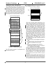
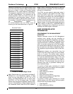
network via transmission of a special frame. Once
the ST201 has been placed in Magic Packet mode
and put to sleep, it scans all incoming frames
addressed to it for a data sequence consisting of
16 consecutive repetitions of its own 48-bit Ether-
net MAC StationAddress. This sequence can be
located anywhere within the frame, but must be
preceded by a synchronization stream. The syn-
chronization stream is defined as 6 bytes of 0xFF.
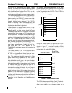
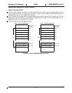
For example, if the MAC address programmed into
the StationAddress register is
0x11:22:33:44:55:66, then the ST201 would be
scanning for the frame data shown in Figure 8.
Magic Packet wake up is controlled by the MagicP-
ktEnable bit in the WakeEvent register. A wake
event can only take place in the D1, D2, or D3
states, and MagicPktEnable has no effect when
the ST201 is in the D0 power state. The Magic
Packet must also pass the address matching crite-
ria set in ReceiveMode. A Magic Packet may also
be a broadcast frame. When the ST201 detects a
Magic Packet, it signals a wake event on PMEN (if
PMEN assertion is enabled), and sets the MagicP-
ktEvent bit in WakeEvent.
The ST201 can also signal a wake event when it
senses a change in the network link state, either
from LINK_OK to LINK_FAIL, or vice versa. Link
state wake is controlled by the LinkEventEnable bit
in the WakeEvent register. At the time LinkEven-
tEnable is set by the host system, the ST201 sam-
ples the current link state. It then waits for the link
state to change. If the link state changes before the
ST201 returns to state D0 or LinkEventEnable is
cleared, LinkEvent is set in WakeEvent, and (if it is
enabled) the PMEN signal is asserted.
HOST SYSTEM RELATED
INFORMATION
PROGRAMMING THE MII MANAGEMENT
INTERFACE
Register accesses across the MII Management
Interface occur serially, and are controlled by
manipulating the MgmtClk, MgmtData, and Mgmt-
Dir bits in the PhyCtrl register. The direction of the
serial transmission is controlled by MgmtDir. Mgm-
mtDir is set when writing bits to the PHY device,
and cleared when reading bits from the PHY. Data
bits are read from and written to MgmtData. Mgmt-
Clk supplies the synchronization clock for the inter-
face.
Management frames are transmitted from the
ST201 to the PHY device using one or more Read,
Write, or Z cycles. The actions which must be
taken by the host system to perform a Read, Write,
or Z cycle are described below. Note, in the cycle
descriptions below, time delays of 200ns can gen-
erally be assumed from back-to back I/O cycles on
the PCI bus. The host system may also use an
arbitrarily long timer to guarantee meeting mini-
mum transition delays.
To perform a Read cycle, consisting of a single
data bit read from the PHY device, the host system
must follow the procedure below.
1. Clear MgmtClk
2. Wait a minimum of 200 ns
3. Set MgmtClk
4. Wait a minimum of 200 ns
5. Read the next data bit from MgmtData
6. Wait a minimum of 200 ns
To perform a Write cycle, consisting of a single
data bit written to the PHY device, the host system
should follow the procedure below.
1. Clear MgmtClk
2. Wait a minimum of 200 ns
0xFFFFFFFFFFFF
Received Packet
FIGURE 8: Example Magic Packet
0x112233445566
0x112233445566
0x112233445566
0x112233445566
0x112233445566
0x112233445566
0x112233445566
0x112233445566
0x112233445566
0x112233445566
0x112233445566
0x112233445566
0x112233445566
0x112233445566
0x112233445566
0x112233445566