


21
Sundance Technology ST201 PRELIMINARY draft 2
D1, D2, or D3. When the ST201 detects a Wake
Packet, it signals a wake event on PMEN (if PMEN
assertion is enabled), and sets the WakePktEvent
bit in the WakeEvent register. The ST201 can sig-
nal that a wake event has occurred when it
receives a pre-defined frame from another station.
The host system transfers a set of frame data pat-
terns into the TxFIFO using the TxDMA function
before placing the ST201 in a power-down state.
Once powered down, the ST201 compares receive
frames with the frame patterns in the TxFIFO.
When a matching frame is received (and also
passes the filtering mode set in the ReceiveMode
register), a wake event is signaled.
Frame patterns are written to the TxFIFO in a sin-
gle “pseudo-packet”. Prior to transferring this
pseudo-packet, the host system should first issue
TxReset (to reset the TxFIFO pointers and prevent
transmission) then prepare a TFD that points to a
single data buffer. The buffer should contain one or
more frame patterns placed contiguously. The
number of frame patterns is limited by the TxFIFO
size. The TxDMAFragLen field in the TFD must
exactly equal the sum of the frame pattern bytes.
Also, the host system must set WordAlign to ‘x1’ in
the TransmitFrameControl field of the TFD to pre-
vent frame word-alignment. Finally, the host sys-
tem must write the TFD’s address to the
TxDMAListPtr register to transfer the frame into the
TxFIFO.
The frame patterns in the TxFIFO specify which
bytes in the incoming frames are to be examined.
A CRC is calculated over these bytes and com-
pared with a CRC value supplied in the frame pat-
tern. This matching technique may result in false
wake events being reported to the host system.
Each wake packet pattern contains one or more
byte-offset/byte-count pairs, an end-of-pattern
symbol, and a 4-byte CRC value. The byte-offset
indicates the number of frame bytes to be skipped
in order to reach the next group of bytes to be
included in the CRC calculation. The byte-count
indicates the number of bytes in the next group to
be included in the CRC calculation. End-of pattern,
which is a byte value of 00, indicates the end of the
pattern for that wake frame. Immediately following
the end-of-pattern is a 4-byte CRC. The CRC cal-
culation uses the same polynomial as the Ethernet
MAC FCS. The pseudo packet frame patterns are
described in the Registers and Data Structures
section.
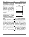
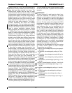
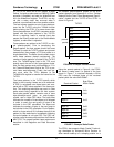
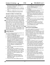
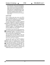
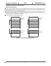
An example pseudo-packet (based on the ARP
packet example from Appendix A of the “OnNow
Network Device Class Power Management Specifi-
cation”) loaded into the TxFIFO of the ST201 is
shown in Figure 6.
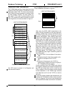
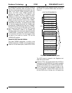
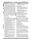
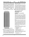
Using the pseudo packet in Figure 6, the ST201
will assert a wake event if a packet of the form
shown in Figure 7 is received whereby a 32-bit
CRC over the indicated bytes of the received
packet yields the value 0xf31908d7.
The ST201 also supports Magic Packet™ technol-
ogy developed by Advanced Micro Devices to
allow remote wake-up of a sleeping station on a
0xc2
0x71
0xf4
0x10
0xf3
0x19
0x08
0xd7
TXFIFO
psuedo
FIGURE 6: Example Psuedo Packet
packet
0x00
byte 12
Received Packet
FIGURE 7: Example Wake Packet
byte 13
0x0c
0x0d
byte 21 0x15
byte 38
byte 39
0x26
0x27
byte 40
byte 41
0x28
0x29
Byte Offset
Within Packet