


1-4
A+ SERVER 1012G-MTF USER'S MANUAL
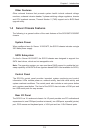
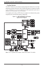
Figure 1-1. AMD SR5650/SP5100 Chipset:
System Block Diagram
Cooling System
The SC813 chassis has an innovative cooling design that features four 4-cm high-
performance system cooling fans. Each of these fans plug into a chassis fan header
on the motherboard. An air shroud channels the airow generated by the fans to
efciently cool the processor area of the system.
A fan speed control setting in BIOS allows fan speed to be determined by system
temperature [the recommended setting is Balanced].
Note: This is a general block diagram. Please see Chapter 5 for details.
DIMM1B
DIMM1A
CPU1
HT3 Link
16/16-2.6 GHz
DIMM2B
DIMM2A
DIMM3B
DIMM3A
DIMM4B
DIMM4A
PCI SLOT1
PCI-E GEN2 X8
Slot6 PCIE x8/x16
IDE (ATA/133)
SA
TA x6
PCI-E GEN2 X8
Slot5 x8
PCI-E GEN2 x1
INTEL
82574L
RJ45
A-Link
SP5100
BMC
VGA
WPCM450-R
PCI
LPC
SMBus
SIO
W83527HG
HWM
W83795G
SPI Flash
KB/MS
COM2
RMII
DDR2 SDRAM
64MB X16
PSU I2C
IPMB
FE PHY
RTL8201N
VGA
RJ45
Clock Gen
TPM
SR5650
COM1
RJ45
INTEL
82574L
PCI SLOT2
PCI SLOT3
PCI-E GEN2 X4
Slot4
SWITCH
PCI-E GEN2 x1
8xUSB