


6-2
A+ SERVER 1012G-MTF USER'S MANUAL
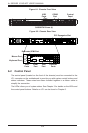
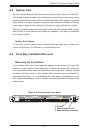
Figure 6-2. Chassis Rear View
6-2 Control Panel
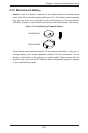
The control panel (located on the front of the chassis) must be connected to the
JF1 connector on the motherboard to provide you with system control buttons and
status indicators. These wires have been bundled together in a ribbon cable to
simplify the connection.
The LEDs inform you of system status. See Chapter 3 for details on the LEDs and
the control panel buttons. Details on JF1 can be found in Chapter 5.
Figure 6-1. Chassis Front View
USB
Ports
SAS/SATA Drives (4)
COM2
Port
Control
Panel
PCI Expansion Slot
Keyboard Port
USB
Ports
COM1
Port
Ethernet
Ports
Dedicated IPMI Port
Mouse Port
VGA
Port