


5-10
A+ SERVER 1012G-MTF USER'S MANUAL
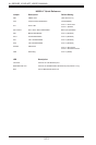
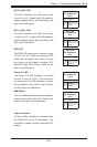
Note 2: Due to memory allocation to system devices, the amount of memory that
remains available for operational use will be reduced when 4 GB of RAM is used.
The reduction in memory availability is disproportional.
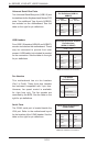
Possible System Memory Allocation & Availability
System Device Size Physical Memory Available
(4 GB Total System Memory)
Firmware Hub ash memory (System BIOS) 1 MB 3.99 GB
Local APIC 4 KB 3.99 GB
Area Reserved for the chipset 2 MB 3.99 GB
I/O APIC (4 Kbytes) 4 KB 3.99 GB
PCI Enumeration Area 1 256 MB 3.76 GB
PCI Express (256 MB) 256 MB 3.51 GB
PCI Enumeration Area 2 (if needed) - aligned on
256 MB boundary
512 MB 3.01 GB
VGA Memory 16 MB 2.85 GB
TSEG 1 MB 2.84 GB
Memory available for the OS & other applications 2.84 GB
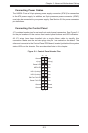
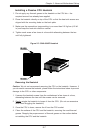
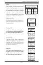
5-7 Adding PCI Expansion Cards
The SC813MTS-350CBP chassis can accommodate one full-size PCI-Express or
PCI expansion card with the use of a PCI riser card.
Installing an Expansion Card
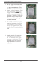
1. After powering down the system, remove the PCI slot shield.
2. Conrm that you have the correct riser card for your chassis model and the
expansion card includes a standard bracket.
3. Remove the chassis cover.
4. Install the riser card by sliding it into the appropriate socket in the
motherboard.
5. Choose the PCI slot shield in which to place the expansion card.
6. In that slot, open the PCI slot shield lever and slide the shield sideways.
7. From inside the chassis, remove the PCI slot shield.
8. Slide the expansion card into the riser card and attach the expansion card
bracket in place of the PCI slot shield.
9. Secure the expansion card by closing the PCI slot shield lever.
10. Connect cables to the expansion card as necessary.