


Chapter 5: Advanced Motherboard Setup
5-17
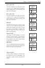
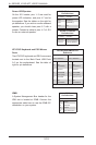
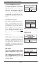
Wake-On-LAN
The Wake-On-LAN header is designated
JWOL. See the table on the right for pin
denitions. You must have a LAN card with
a Wake-On-LAN connector and cable to use
the Wake-On-LAN feature.
Wake-On-LAN
Pin Denitions
(JWOL)
Pin# Denition
1 +5V Standby
2 Ground
3 Wake-up
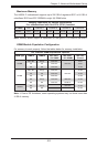
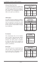
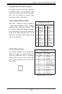
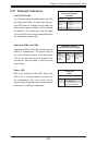
SGPIO
The T-SGPIO1/ T-SGPIO2 (Serial General
Purpose Input/Output) headers provide
a bus between the SATA controller and
the backpane to provide SATA enclosure
management functions. Connect the
appropriate cable from the backplane
to the T-SGPIO1 header to utilize SATA
management functions on your system.
SGPIO Header Pin Denitions
(T-SGPIO1/T-SGPIO2)
Pin# Denition Pin # Denition
1 NC 2 Data
3 Ground 4 Data
5 Load 6 Ground
7 CLK 8 NC
Note: NC indicates no connection.
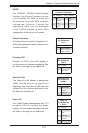
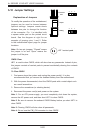
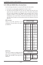
Power I2C
The Power System Management Bus (I
2
C)
connector (JPI
2
C1) monitors the power
suppply, fan and system temperatures. See
the table on the right for pin denitions.
Power I
2
C
Pin Denitions
(JPI2C)
Pin# Denition
1 Clock
2 Data
3 PWR Fail
4 Ground
5 +3.3V
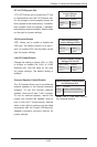
Chassis Intrusion
A Chassis Intrusion header is located at JL1.
Attach the appropriate cable to inform you of
a chassis intrusion.
Chassis Intrusion
Pin Denitions
(JL1)
Pin# Denition
1 Battery voltage
2 Intrusion signal
Overheat LED
Connect an LED to the JOH1 header to
provide warning of chassis overheating. See
the table on the right for pin denitions.
Overheat LED
Pin Denitions
(JOH1)
Pin# Denition
1 3.3V
2 OH Active