


5-18
A+ SERVER 1012G-MTF USER'S MANUAL
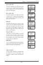
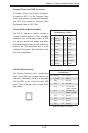
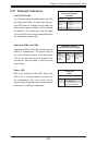
ATX PS/2 Keyboard and PS/2 Mouse
Ports
The ATX PS/2 keyboard and PS/2 mouse are
located next to the Back Panel USB Ports
0~3 on the motherboard. See the table at
right for pin denitions.
PS/2 Keyboard/Mouse Pin
Denitions
PS2 Keyboard PS2 Mouse
Pin# Denition Pin# Denition
1 KB Data 1 Mouse Data
2 No
Connection
2 No
Connection
3 Ground 3 Ground
4 Mouse/KB
VCC (+5V)
4 Mouse/KB
VCC (+5V)
5 KB Clock 5 Mouse Clock
6 No
Connection
6 No
Connection
VCC: with 1.5A PTC (current limit)
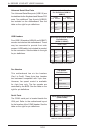
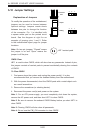
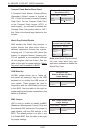
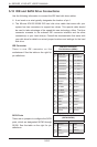
Power LED/Speaker
On the JD1 header, pins 1~3 are used for
power LED indication, and pins 4-7 are for
the speaker. See the tables on the right for
pin denitions. If you wish to use the onboard
speaker, you should close pins 6~7 with a
jumper. Connect a cable to pins 4~7 of JD1
to use an external speaker.
Speaker Connector
Pin Denitions
Pin Setting Denition
Pins 4~7 External Speaker
Pins 6~7 Internal Speaker
PWR LED Connector
Pin Denitions
Pin Setting Denition
Pin 1 Anode (+)
Pin2 Cathode (-)
Pin3 NA
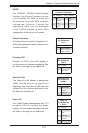
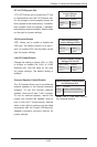
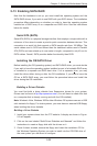
IPMB
A System Management Bus header for the
IPMI slot is located at IPMB. Connect the
appropriate cable here to use the IPMB I2C
connection on your system.
IPMB
Pin Denitions
Pin# Denition
1 Data
2 Ground
3 Clock
4 No Connection