


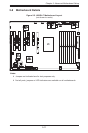


Chapter 5: Advanced Motherboard Setup
5-19
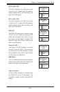
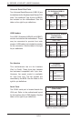
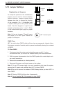
Compact Flash Card PWR Connector
A Compact Flash Card Power Connector
is located at JWF1. For the Compact Flash
Card to work properly, you will need to enable
with JCF1 and connect a Compact Flash
Card power cable to JWF1 rst.
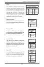
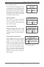
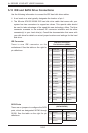
Trusted Platform Module Header
The JLPC1 header is used to connect a
Trusted Platform Module (TPM), available
separately from a third-party vendor. A TPM
is a security device that allows encryption
and authentication of hard drives, disallowing
access if the TPM associated with it is not
installed in the system. See the table on the
right for pin denitions.
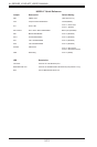
Trusted Platform Module Header
Pin Denitions (JLPC1 )
Pin# Denition Pin# Denition
1 LCLK 2 GND
3 LFRAME 4 No Pin
5 LRESET 6 VCC5
7 LAD3 8 LAD2
9 VCC3 10 LAD1
11 LAD0 12 GND
13 RSV0 14 RSV1
15 SB3V 16 SERIRQ
17 GND 18 CLKRUN
19 LPCPD 20 RSV2
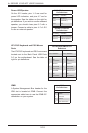
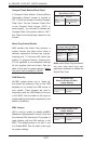
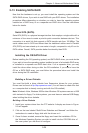
LAN1/2 (Ethernet Ports)
Two Gigabit Ethernet ports (designated
LAN1 and LAN2) are located beside the
VGA port. Additionally, there is a dedicated
LAN for IPMI on top of the two rear USB
ports. These Ethernet ports accept RJ45
type cables.
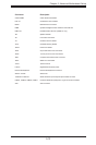
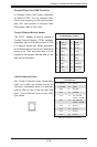
LAN Ports (LAN1/2)
Pin Denition
Pin# Denition Pin# Denition
1 P2V5SB 10 SGND
2 TD0+ 11 Act LED
3 TD0- 12 P3V3SB
4 TD1+ 13 Link 100 LED
(Yellow, +3V3SB)
5 TD1- 14 Link 1000 LED
(Yellow, +3V3SB)
6 TD2+ 15 Ground
7 TD2- 16 Ground
8 TD3+ 17 Ground
9 TD3- 18 Ground
Note: NC indicates no connection.