


5-2
A+ SERVER 1012G-MTF USER'S MANUAL
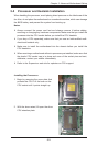
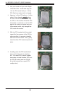
5-2 Motherboard Installation
This section describes mounting the H8SGL-F into the SC813MTS-350CBP chassis.
Be sure theh chassis is not connected to AC power.
Installing to the Motherboard
1. Remove the the chassis cover.
2. Make sure that the I/O ports on the motherboard align properly with their
respective holes in the I/O shield at the back of the chassis.
3. Carefully mount the motherboard to the motherboard tray by aligning the
board holes with the raised metal standoffs that are visible in the chassis. You
may need to add an extra standoff for the hole near the Fan 3 header.
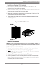
4. Insert screws into all the mounting holes on your motherboard that line up
with the standoffs and tighten until snug. Do not apply force greater than 8
inch-lbs. of torque.
Note: Metal screws provide an electrical contact to the motherboard ground.
Caution: Do not operate the server for long without the cover. It is required for
proper airow and cooling.
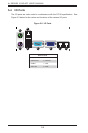
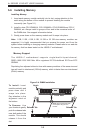
5-3 Connecting Cables
Now that the motherboard is installed, the next step is to connect the cables to the
board. These include the data (ribbon) cables for the peripherals and control panel
and the power cables.
Connecting Data Cables
The cables used to transfer data from the peripheral devices have been carefully
routed to prevent them from blocking the ow of cooling air that moves through
the system from front to back. If you need to disconnect any of these cables, you
should take care to keep them routed as they were originally after reconnecting
them (make sure the red wires connect to the pin 1 locations). The following
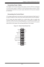
data cables (with their locations noted) should be connected. (See the layout on
page 5-9 for connector locations.)
•Control Panel cable (JF1)
•COM Port cable (COM2)
•Front USB port cable (USB2/3)
Important! Make sure the the cables do not come into contact with the fans.