


5-24
A+ SERVER 1012G-MTF USER'S MANUAL
5-12 IDE and SATA Drive Connections
Use the following information to connect the IDE hard disk drive cables.
•A red mark on a wire typically designates the location of pin 1.
•The 80-wire ATA133/100/66 IDE hard disk drive cable that came with your
system has two connectors to support two drives. This special cable should
be used to take advantage of the speed this new technology offers. The blue
connector connects to the onboard IDE connector interface and the other
connector(s) to your hard drive(s). Consult the documentation that came with
your disk drive for details on actual jumper locations and settings for the hard
disk drive.
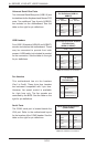
IDE Drive Connector
Pin Denitions (IDE#1)
Pin# Denition Pin # Denition
1 Reset IDE 2 Ground
3 Host Data 7 4 Host Data 8
5 Host Data 6 6 Host Data 9
7 Host Data 5 8 Host Data 10
9 Host Data 4 10 Host Data 11
11 Host Data 3 12 Host Data 12
13 Host Data 2 14 Host Data 13
15 Host Data 1 16 Host Data 14
17 Host Data 0 18 Host Data 15
19 Ground 20 Key
21 DRQ3 22 Ground
23 I/O Write 24 Ground
25 I/O Read 26 Ground
27 IOCHRDY 28 BALE
29 DACK3 30 Ground
31 IRQ14 32 IOCS16
33 Addr1 34 Ground
35 Addr0 36 Addr2
37 Chip Select 0 38 Chip Select 1
39 Activity 40 Ground
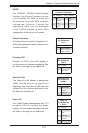
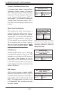
SATA Ports
There are no jumpers to congure the SATA
ports, which are designated SATA0 through
SATA5. See the table on the right for pin
denitions.
SATA Ports Pin Denitions
(SATA0-SATA5)
Pin # Denition Pin # Denition
1 Ground 5 RXN
2 TXP 6 RXP
3 TXN 7 Ground
4 Ground
IDE Connector
There is one IDE connector on the
motherboard. See the table on the right for
pin denitions.