


Chapter 5: Advanced Serverboard Setup
5-3
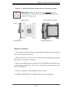
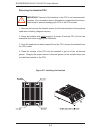
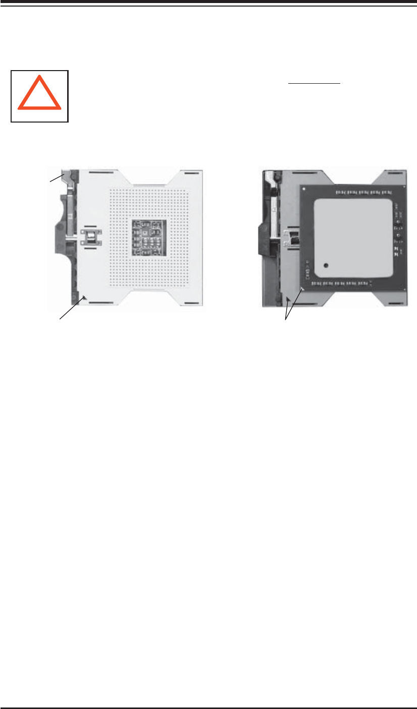
Figure 5-1. 604-pin PGA Socket: Empty and with Processor Installed
Warning! Make sure you lift the lever completely when in-
stalling the CPU. If the lever is only partly raised, damage to the
socket or CPU may result.
!
Lever
With processor installed
Triangle (pin 1)
Empty socket
Triangle locating pin 1
Heatsink Installation
1. Do not apply any thermal compound to the heatsink or the CPU die; the required
amount has already been applied.
2. Place the heatsink on top of the CPU so that the four mounting holes are aligned
with those on the retention mechanism.
3. Screw in two diagonal screws until snug (do not fully tighten the screws to avoid
possible damage to the CPU). Then screw in the other two diagonal screws until
snug. See Figure 5-2.
4. Finish the installation by fully tightening all four screws.
*The heatsink (SNK-P0009) is an optional item that is sold separately.