


Chapter 5: Advanced Serverboard Setup
5-15
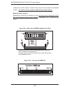
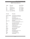
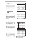
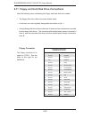
Fan Headers
There are ten fan headers (FAN1-
FAN10) on the X6DHP-TG. These
fans use DC power. See the table on
the right for fan pin defi nitions.
Note: Fan speed is controlled by the
"Fan Speed Control Mode" setting in
BIOS (see page 7-16).
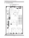
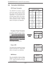
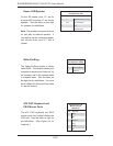
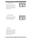
Universal Serial Bus
(USB0/1)
Two USB 2.0 ports are located beside
the GLAN (Ethernet) ports. USB0 is
the bottom port and USB1 is the top
port. See the table on the right for
pin defi nitions.
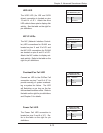
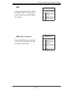
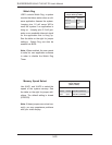
Universal Serial Bus
Headers
Two extra USB headers (at FPUSB2/
FPUSB3) can be used for front side
USB access. You will need a USB
cable to use these connections. Re-
fer to the tables on the right for pin
defi nitions.
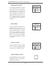
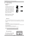
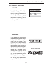
Serial Ports
There are two COM headers (JCOM1
and JCOM2) located between the
Marvell SATA ports and the fl oppy
connector. See the table on the right
for pin defi nitions.
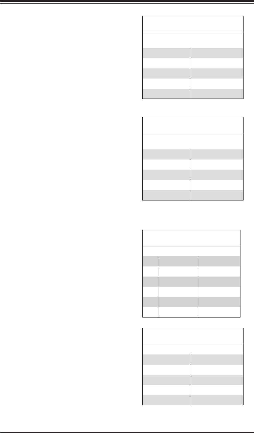
Universal Serial Bus
Pin Defi nitions (USB0/1)
USB0
Pin # Defi nition
USB1
Pin # Defi nition
1 +5V 1 +5V
2 PO- 2 PO-
3 PO+ 3 PO+
4 Ground 4 Ground
5 N/A 5 Key
Fan Header
Pin Defi nitions (Fan1-10)
Pin# Defi nition Color
1 Fan Power Red
2 Tachometer Yellow
3 Ground Black
4 Ground Grey
5 Tachometer White
6 Fan Power Orange
Front Panel Universal Serial Bus
Pin Defi nitions (USB2/3)
USB2
Pin # Defi nition
USB3
Pin # Defi nition
1 +5V 1 +5V
2 PO- 2 PO-
3 PO+ 3 PO+
4 Ground 4 Ground
5 N/A 5 N/A
Serial Port Pin Defi nitions
(JCOM1/JCOM2)
Pin # Defi nition Pin # Defi nition
1 DCD 6 DSR
2 RXD 7 RTS
3 TXD 8 CTS
4 DTR 9 RI
5 Ground 10 NC
Note: Pin 10 is included on the header but not on
the port. NC indicates no connection.