


Chapter 5: Advanced Serverboard Setup
5-13
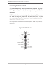
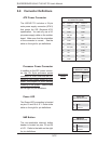
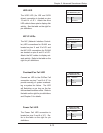
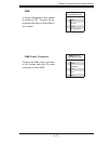
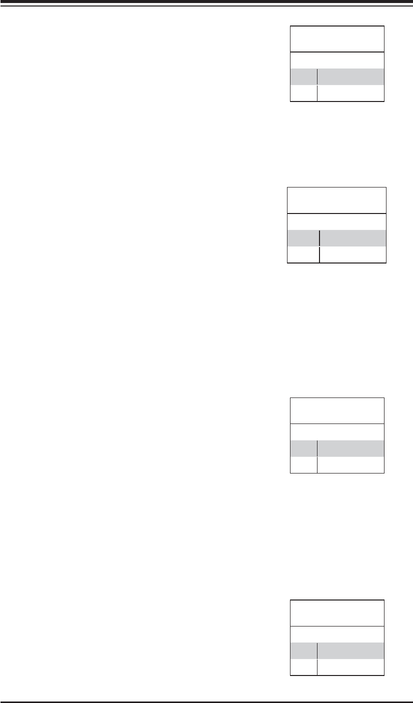
Overheat/Fan Fail LED
Connect an LED to the OH/Fan Fail
connection on pins 7 and 8 of JF1 to
provide warning of system overheat-
ing or system fan failure. The LED
will fl ash/stay on as long as the fan
fail/overheat condition exists. Refer to
the table on the right for pin defi nitions
and Chapter 3 for details.
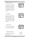
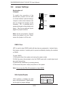
NIC1/2 LEDs
The NIC (Network Interface Control-
ler) LED connections for GLAN1 are
located on pins 11 and 12 of JF1 and
the NIC LED connections for GLAN2
are located on pins 9 and 10 of JF1.
Attach the NIC cables to display net-
work activity. Refer to the table on the
right for pin defi nitions.
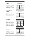
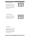
HDD LED
The HDD LED (for IDE and SATA
drives) connection is located on pins
13 and 14 of JF1. Attach the drive
LED cable to these pins to display disk
activity. See the table on the right for
pin defi nitions.
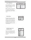
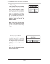
Power Fail LED
The Power Fail LED connection is
located on pins 5 and 6 of JF1. Re-
fer to the table on the right for pin
defi nitions.
HDD LED
Pin Defi nitions (JF1)
Pin# Defi nition
13 Vcc
14 HD Active
NIC1 LED
Pin Defi nitions (JF1)
Pin# Defi nition
9/11 Vcc
10/12 Ground
OH/Fan Fail LED
Pin Defi nitions (JF1)
Pin# Defi nition
7 Vcc
8 Ground
Power Fail LED
Pin Defi nitions (JF1)
Pin# Defi nition
5 Vcc
6 Ground