


5-12
S
UPERSERVER 6014P-T/6014P-TR User's Manual
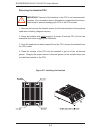
5-8 Connector Defi nitions
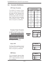
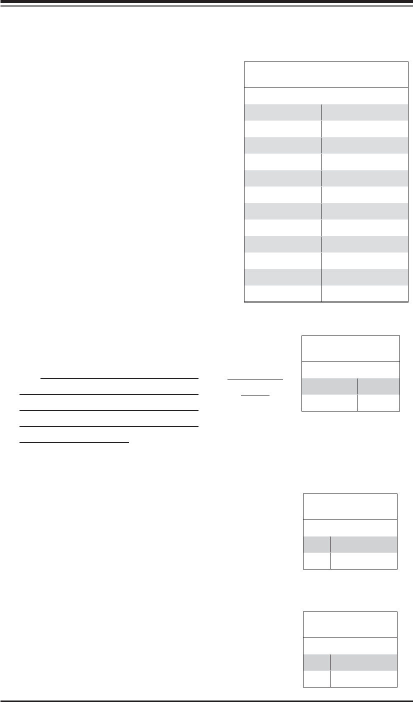
ATX Power Connector
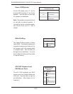
The X6DHP-TG includes a 24-pin
main power supply connector (JPW1)
that meets the SSI (Superset ATX)
specifi cation. You can only use a 24-
pin power supply cable on the mother-
board. Make sure that the orientation
of the connector is correct. See the
table on the right for pin defi nitions.
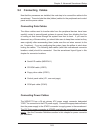
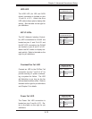
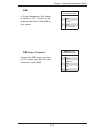
Processor Power Connector
In addition to the ATX power connec-
tor, the 12v 8-pin processor power
connector at JPW2 must also be con-
nected to your power supply for CPU
power consumption to avoid causing
instability to the system. See the table
on the right for pin defi nitions.
Required Con-
nection
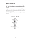
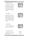
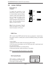
NMI Button
The non-maskable interrupt button
header is located on pins 19 and 20
of JF1. Refer to the table on the right
for pin defi nitions.
ATX Power 24-pin Connector
Pin Defi nitions (JPW1)
Pin# Defi nition Pin # Defi nition
13 +3.3V 1 +3.3V
14 -12V 2 +3.3V
15 COM 3 COM
16 PS_ON 4 +5V
17 COM 5 COM
18 COM 6 +5V
19 COM 7 COM
20 Res (NC) 8 PWR_OK
21 +5V 9 5VSB
22 +5V 10 +12V
23 +5V 11 +12V
24 COM 12 +3.3V
Processor Power
Pin Defi nitions (JPW2)
Pins Defi nition
1 through 4 Ground
5 through 8 +12V
NMI Button
Pin Defi nitions (JF1)
Pin# Defi nition
19 Control
20 Ground
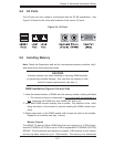
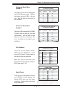
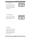
Power LED
The Power LED connection is located
on pins 15 and 16 of JF1. Refer to the
table on the right for pin defi nitions.
Power LED
Pin Defi nitions (JF1)
Pin# Defi nition
15 Vcc
16 Control