


5-16
S
UPERSERVER 6014P-T/6014P-TR User's Manual
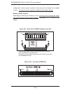
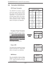
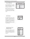
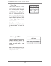
Power LED/Speaker
On the JDI header, pins 1-3 are for
a power LED and pins 4-7 are for the
speaker. See the table on the right
for speaker pin defi nitions.
Note: The speaker connector pins are
for use with an external speaker. If
you wish to use the onboard speaker,
you should close pins 6-7 with a
jumper.
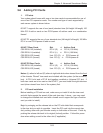
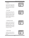
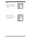
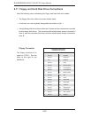
Wake-On-Ring
The Wake-On-Ring header is desig-
nated WOR. This function allows your
computer to receive and "wake-up" by
an incoming call to the modem when
in suspend state. See the table on
the right for pin defi nitions. You must
have a Wake-On-Ring card and cable
to use this feature.
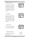
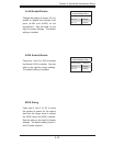
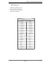
ATX PS/2 Keyboard and
PS/2 Mouse Ports
The ATX PS/2 keyboard and PS/2
mouse ports are located beside the
VGA port. See the table at right for
pin defi nitions. (See Figure 5-4 for
locations.)
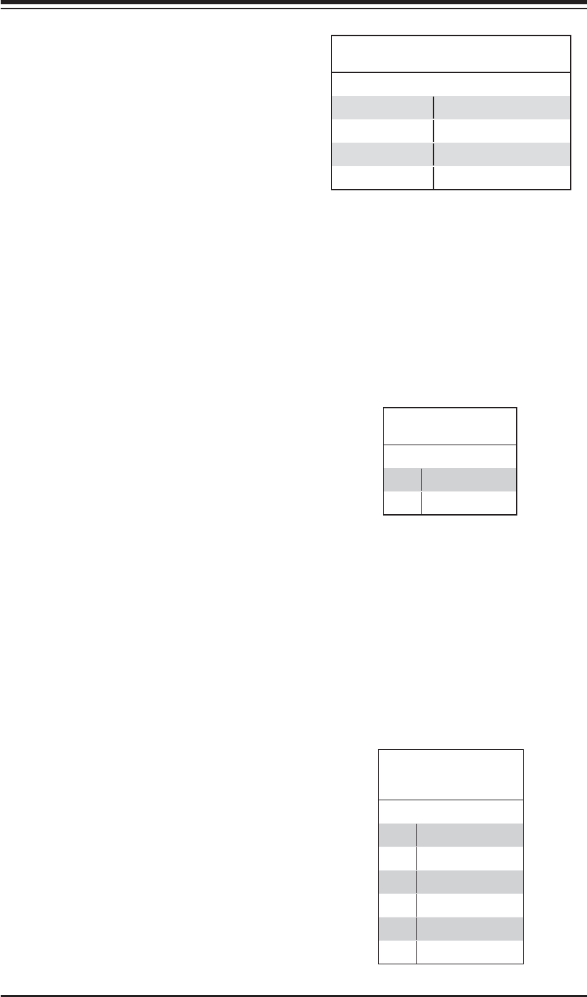
Speaker Connector
Pin Defi nitions (JD1)
Pin # Function Defi nition
4 + Speaker data (red wire)
5 Key No connection
6 Key
7 Speaker data
Wake-On-Ring
Pin Defi nitions (WOR)
Pin# Defi nition
1 Ground (Black)
2 Wake-up
PS/2 Keyboard and
Mouse Port Pin
Defi nitions
Pin# Defi nition
1 Data
2NC
3 Ground
4 VCC
5 Clock
6NC