


5-14
S
UPERSERVER 6014P-T/6014P-TR User's Manual
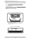
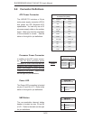
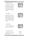
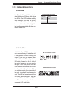
JLAN1/2 (Ethernet Ports)
Two gigabit Ethernet ports are located
beside the VGA port. These ports ac-
cept RJ45 type cables.
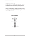
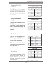
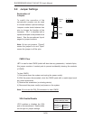
Power Button
The Power Button connection is
located on pins 1 and 2 of JF1. Mo-
mentarily contacting both pins will
power on/off the system. This button
can also be confi gured to function
as a suspend button (see setting in
BIOS). To turn off power in suspend
mode, depress the button for at least
4 seconds.
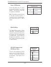
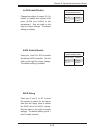
Chassis Intrusion
A Chassis Intrusion header is located
at JL1. Attach the appropriate cable
to inform you of a chassis intrusion.
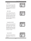
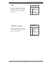
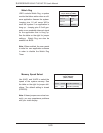
UID Button & UID LED
A Unit Identifi er button/LED is located
next to the VGA port on the rear of
the chassis and a UID LED and
button (separate) are located on the
front control panel. The UID LED con-
nection is located on pins 3 and 4 of
JF1. Refer to the table on the right
for pin defi nitions and to page 5-21
for details.
UID & UID_LED
Pin Defi nitions (JF1)
Pin# Defi nition
3 Front UID
4 UID_LED
Power Button
Pin Defi nitions (JF1)
Pin# Defi nition
1PW_ON
2 Ground
Chassis Intrusion
Pin Defi nitions (JL1)
Pin# Defi nition
1 Intrusion Input
2 Ground