


6-2
S
UPERSERVER 6014P-T/6014P-TR User's Manual
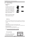
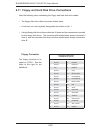
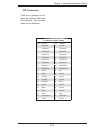
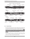
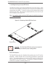
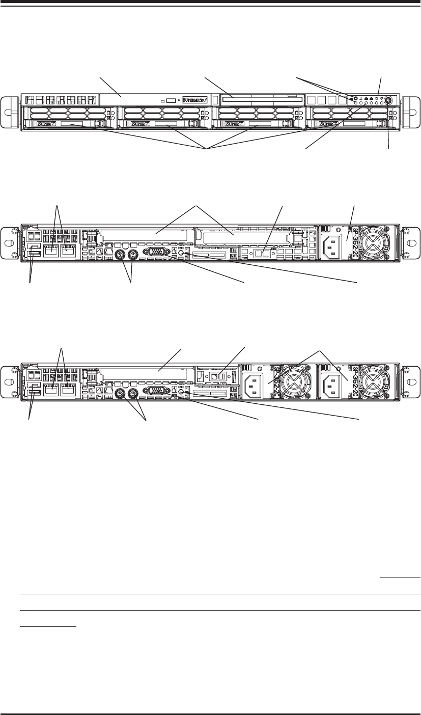
Figure 6-1. Chassis: Front and Rear Views
UID Button and LED
6-2 Control Panel
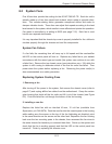
The control panel (located on the front of the chassis) must be connected to the
JF1 connector on the serverboard to provide you with system status indications. A
ribbon cable has bundled these wires together to simplify the connection. Connect
the cable from JF1 on the serverboard to the appropriate header on the Control
Panel PCB (printed circuit board). Make sure the red wire plugs into pin 1 on both
connectors. Pull all excess cabling out of the airfl ow path.
The control panel LEDs inform you of system status. See "Chapter 3: System
Interface" for details on the LEDs and the control panel buttons. Details on JF1
can be found in "Chapter 5: Advanced Serverboard Setup."
Control Panel
System LEDs Main Power
Slim DVD-ROM Drive
Slim Floppy Drive
SATA Drives
PCI Expansion Slots Power Supply
VGA PortMouse/Keyboard Ports
GLAN Ports
USB0/1 Ports UID Button/LED
6014P-T
6014P-TR
PCI Expansion Slot Power SuppliesGLAN Ports
VGA PortMouse/Keyboard PortsUSB0/1 Ports UID Button/LED
COM Port
COM Port