


5-6
S
UPERSERVER 6014P-T/6014P-TR User's Manual
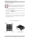
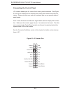
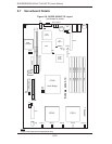
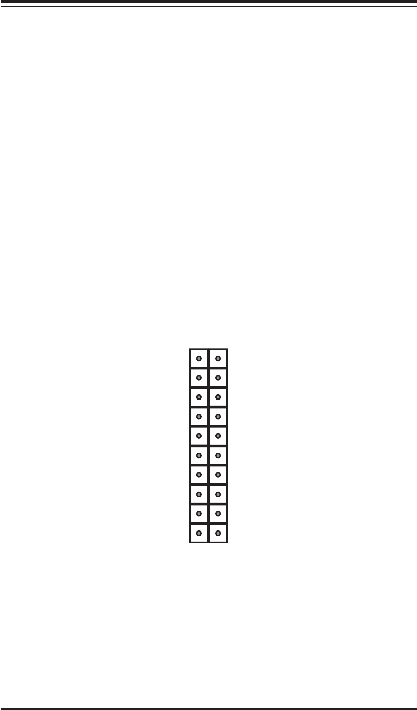
Figure 5-3. JF1 Header Pins
Connecting the Control Panel
JF1 contains header pins for various front control panel connectors. See Figure
5-3 for the pin locations of the various front control panel buttons and LED indi-
cators. Please note that even and odd numbered pins are on opposite sides of
each header.
All JF1 wires have been bundled into single ribbon cable to simplify their connec-
tion. Make sure the red wire plugs into pin 1 as marked on the board. The other
end connects to the Control Panel printed circuit board, located just behind the
system status LEDs in the chassis.
See the Connector Defi nitions section in this chapter for details and pin descrip-
tions of JF1.
NMI
x (key)
Vcc
Vcc
Vcc
Vcc
Vcc
Vcc
Reset Button
Power Button
Ground
x (key)
Power LED
HDD LED
NIC1
NIC2
OH/Fan Fail LED
Power Fail LED
Ground
Ground
2 1
20 19