


2-8
X7DA3+ User's Manual
®
JLAN1
S
U
PE
R
X7D
A
3+
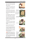
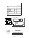
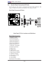
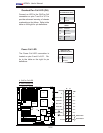
2-5 Control Panel Connectors/IO Ports
The I/O ports are color coded in conformance with the PC 99 specifi cation. See
Figure 2-3 below for the colors and locations of the various I/O ports.
Back Panel Connectors/IO Ports
Back Panel I/O Port Locations and Defi nitions
Back Panel Connectors
1. Keyboard (Purple)
2. PS/2 Mouse (Green)
3. Back Panel USB Port 0
4. Back Panel USB Port 1
5. Back Panel USB Port 2
6. Back Panel USB Port 3
7. COM Port 1 (Turquoise)
8. Parallel Port (Printer)
9. Gigabit LAN 2
10. Gigabit LAN 1
11. Side_Surround (Grey)
12. Back_Surround (Black)
13. CEN/LFE (Orange)
14. Microphone-In (Pink)
15. Front (Green)
16. Line-In (Blue)
(See Section 2-5 for details.)
1
2
3
4
5
6
7
8
9
10
11
12
13
14
15
16