


Chapter 2: Installation
2-17
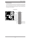
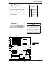
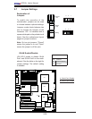
LAN1/2
®
JLAN1
S
UPER X7DA3+
Fan1
8-pin PWR
J
F
1
FP Control
SPK
PW LED
JOH1
Fan3
I
DE1
Floppy
Fan4
SA
T
A
3
SA
TA
5
USB4/5
SMB
P
CI-X
1
00
M
Hz
Z
CR
(G
reen
S
lot)
P
CI
-
X
133 M
Hz
JWD
B
attery
G
L
AN
CTLR
PCI-
Exp x4
Nort
h
Brid
g
e
COM1
Fan
6
Fan
5
AT
X
PWR
4
-Pin
P
WR
J3P
Parrallel
Port
2
4
-Pin
SAS
Controller
P
X
H
CP
U
1
CPU2
South
Bridge
Fan
7
JAR
J17
PSF
JPW2
JPW1
JPW3
Fan
2
C
ompa
ct
Flash
LE
1
Fan8
J
C
F
1
JWF1
SA
TA2
SA
TA
4
SA
TA1
SA
TA0
JL
1
Slot
1
Slot
2
Slot
3
P
CI-X
133
M
Hz
Slot
4
JPL2
S
lot
5
PCI-33MHz
Slot
6
PCI-Exp x16
SIM LP IPMI
Slot
7
D
IMM 1A (B
ank 1)
DIMM 1B
(Bank 1)
D
IMM 2A (B
ank 2)
D
IMM
2B (Ban
k
2)
D
IMM 3A (B
ank 3)
DIMM 3
B (Bank
3
)
D
IMM 4A
(
B
an
k
4)
DIMM
4B
(Bank
4)
JBT1
J
WOL
J
WOR
KB
/
M
ouse
U
S
B
0
/
1/2/3
HD
Audio
J
I
2
C2
J
I
2
C3
J
I
2
C4
G
reencreek
B
I
O
S
CPU
Fan 1
CD1
JPL1
J
I
2
C1
CPU
Fan2
SG
P
IO1
SG
P
IO2
J
S1
0
SAS4-7
SAS0-3
JP
S
1
ACT0
-3
AC
T
4-7
Audio
CTRL
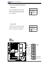
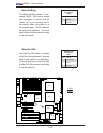
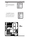
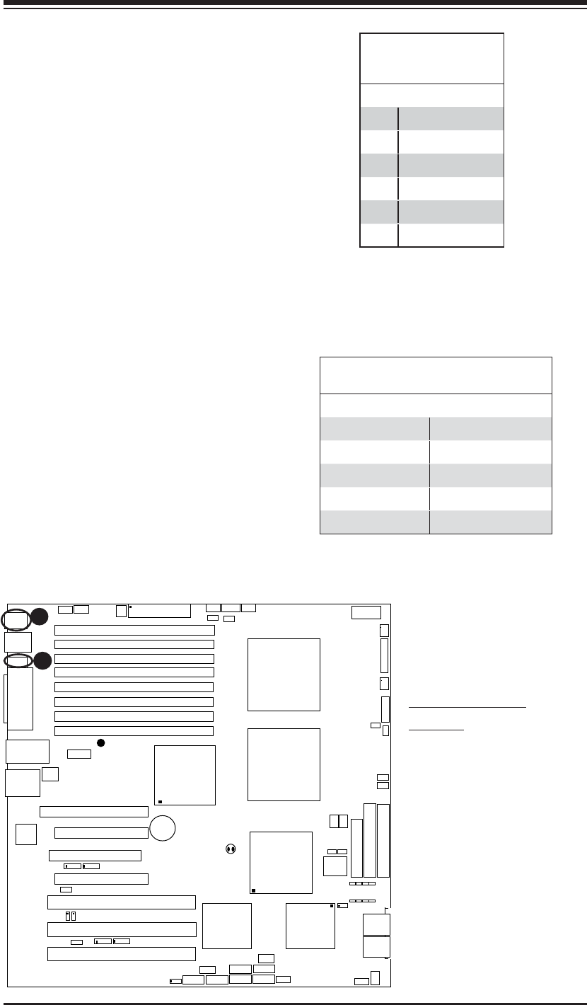
ATX PS/2 Keyboard and
PS/2 Mouse Ports
The ATX PS/2 keyboard and the PS/2
mouse are located at JKM1. See the
table on the right for pin defi nitions.
(The mouse port is above the key-
board port. See the table on the right
for pin defi nitions.)
PS/2 Keyboard and
Mouse Port Pin
Defi nitions
Pin# Defi nition
1Data
2NC
3 Ground
4 VCC
5 Clock
6NC
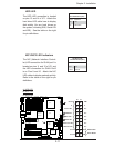
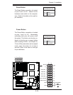
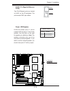
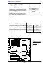
Serial Port
COM1 is a connector located at
JCOM1 on the IO Backpanel. See the
table on the right for pin defi nitions.
Serial Port Pin Defi nitions
(COM1)
Pin # Defi nition Pin # Defi nition
1 CD 6 DSR
2RD 7RTS
3TD 8CTS
4DTR 9RI
5 Ground 10 NC
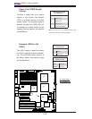
A
B
A. Keyboard/Mouse
B. COM1
( NC: No Connection.)