


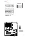
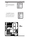
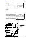
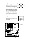
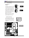
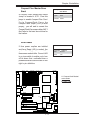
2-20
X7DA3+ User's Manual
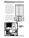
LAN1/2
®
JLAN1
S
UPER X7DA3+
Fan1
8-pin PWR
J
F1
FP Control
SPK
PW LED
JOH1
Fan3
I
DE1
Flopp
y
Fan4
SA
TA3
SATA5
USB4/
5
SM
B
P
CI-X
100 M
Hz Z
CR
(Green
S
lot
)
P
CI
-X
133
M
Hz
JWD
B
atter
y
G
LAN
C
T
LR
PCI-
Exp x4
North
Brid
g
e
COM1
Fan
6
Fan
5
AT
X PWR
4
-Pin
P
WR
J3P
Parrallel
Port
2
4
-Pin
SAS
Controller
PX
H
CPU1
CP
U
2
South
B
rid
ge
Fan
7
JAR
J17
PSF
JPW2
JPW1
JPW3
Fan
2
C
ompa
ct
Flash
LE1
Fan8
J
C
F
1
JWF
1
SATA2
SATA4
SA
T
A
1
SAT
A
0
JL
1
Slot
1
Slot
2
Slot
3
P
CI-X
133 M
Hz
Slot
4
JPL2
Slot
5
PCI-33MHz
S
lot
6
PCI-Exp x16
SIM LP IPMI
Slot
7
D
IMM 1A
(B
an
k
1)
DIMM 1B (Ban
k
1)
D
IMM 2A
(B
an
k
2)
DIMM
2
B (Bank 2)
D
IMM 3A
(
B
ank 3)
DIMM 3B
(Bank
3)
D
I
MM
4
A
(B
an
k 4
)
D
IMM
4B (Ban
k
4)
J
BT1
J
WOL
J
WOR
K
B/
M
ouse
USB
0
/
1/2/3
HD
Audio
J
I
2
C2
J
I
2
C
3
J
I
2
C4
G
reencree
k
B
I
OS
CPU
Fan 1
CD1
JPL1
J
I
2
C1
CPU
Fan2
SG
P
IO1
SG
P
IO2
J
S1
0
SAS
4
-
7
SAS
0
-
3
JP
S
1
AC
T
0-3
ACT4-
7
Audio
CTRL
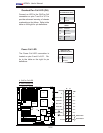
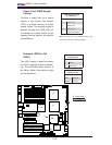
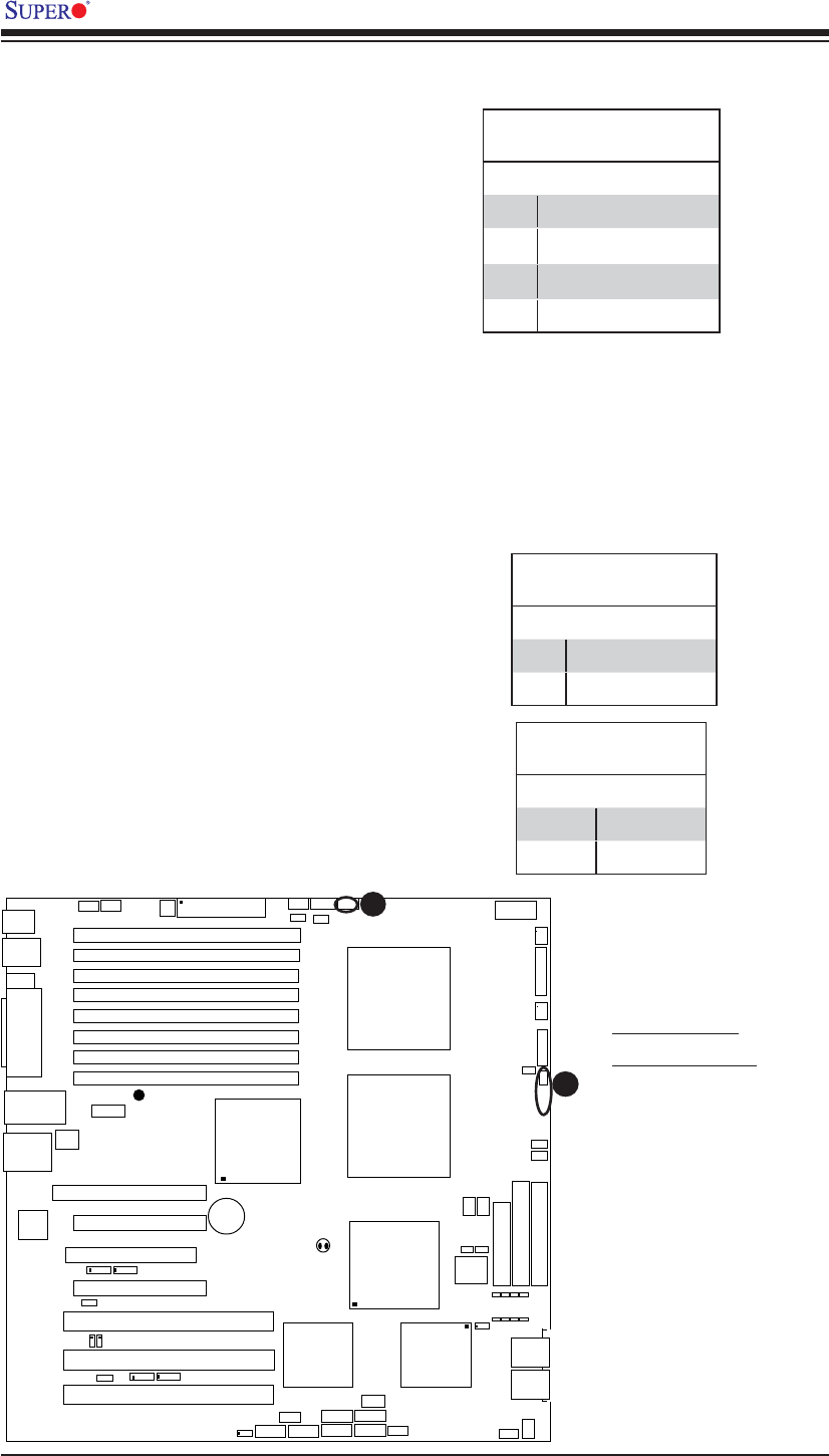
Power Fault (PWR Supply
Failure)
Connect a cable from your power
supply to the Power Fail header
(PSF) to provide warning of power
supply failure. This warning signal is
passed through the PWR_LED pin
to indicate of a power failure on the
chassis. See the table on the right for
pin defi nitions.
Note: This feature is only available when using
Supermicro redundant power supplies.
PWR Supply Fail LED
Pin Defi nitions
Pin# Defi nition
1 PWR 1: Fail
2 PWR 2: Fail
3 PWR 3: Fail
4 Signal: Alarm Reset
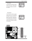
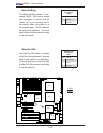
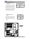
A
B
A. Power Fault
B. Overheat LED
Overheat LED/Fan Fail
(JOH1)
The JOH1 header is used to connect
an LED to indicate chassis overheat-
ing. This LED blinks when there is a
fan failure. Refer to the table on right
for pin defi nitions.
Overheat LED
Pin Defi nitions
Pin# Defi nition
1 5vDC
2 OH Active
OH/Fan Fail LED
State Message
Solid Overheat
Blinking Fan Fail