


Chapter 2: Installation
2-29
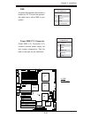
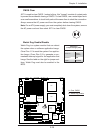
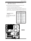
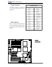
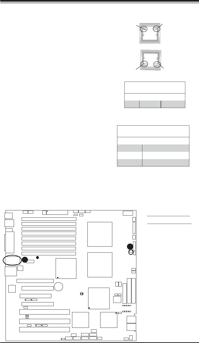
LAN1/2
®
JLAN1
S
UPER X7DA3+
Fan1
8-pin PWR
J
F
1
FP Control
SPK
PW LED
JOH1
Fan3
I
DE1
Floppy
Fan4
SA
TA3
SATA5
USB4/
5
SMB
P
CI-X
100 M
Hz Z
CR
(Green S
lot)
P
CI
-X
133
M
Hz
JWD
B
atter
y
G
L
AN
C
TLR
PCI-
Exp x
4
North
Brid
g
e
COM1
Fan
6
Fan
5
A
T
X PWR
4
-Pin
P
WR
J3P
Parrallel
Port
2
4
-Pin
SAS
Controller
P
X
H
CPU1
CP
U
2
South
B
rid
ge
Fan
7
JAR
J17
PSF
JPW2
JPW1
JPW3
Fan
2
C
ompa
ct
Flash
LE1
Fan8
J
C
F1
JWF1
SATA2
SATA4
SA
TA
1
SA
TA
0
JL
1
Slot
1
Slot
2
Slot
3
P
CI-X
133 M
Hz
Slot
4
JPL2
Slot
5
PCI-33MHz
Slot
6
PCI-Exp x16
SIM LP IPMI
Slot
7
D
I
MM
1
A
(B
an
k 1
)
D
IMM
1B (Ban
k
1)
D
IMM 2A
(B
an
k 2
)
DIMM
2B
(Bank
2)
D
IMM 3A
(B
an
k
3)
DIMM 3B (Bank
3)
D
IMM 4
A
(B
ank 4)
D
I
MM
4B
(B
ank
4)
JBT1
J
WOL
J
WOR
KB/
M
ouse
USB
0
/
1/2/3
HD
Audio
J
I
2
C2
J
I
2
C3
J
I
2
C4
G
reencree
k
B
I
OS
CPU
Fan 1
CD1
JPL1
J
I
2
C1
CPU
Fan2
SG
P
IO1
SG
P
IO2
J
S1
0
SAS
4
-
7
SAS0-3
JP
S
1
AC
T
0-3
ACT4-
7
Audio
CTRL
GLAN LEDs
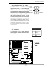
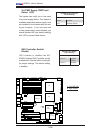
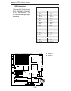
There are two GLAN ports on the moth-
erboard. Each Gigabit Ethernet LAN port
has two LEDs. The green LED indicates
activity, while the Link LED may be green,
amber or off to indicate the speed of the
connection. See the tables at right for
more information.
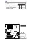
2-8 Onboard Indicators
Activity
LED
GLAN Activity Indicator
Color Status Defi nition
Green Flashing Active
GLAN Link Indicator
LED Color Defi nition
Off No Connection or 10 Mbps
Green (On) 100 Mbps
Amber (On) 1 Gbps
A
B
A. GLAN Port1 LEDs
B. Standby PWR LED
Link
LED
Activity
LED
Link
LED
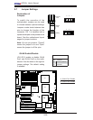
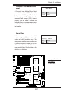
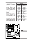
Onboard Power LED
There is an Onboard Power LED located
on the motherboard. When this LED is
lit, the onboard power is on. Be sure to
turn off the system and unplug the power
cord before removing or installing com-
ponents. See the layout below for the
LED location.