


Chapter 2: Installation
2-31
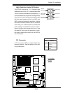
LAN1/2
®
JLAN1
S
UPER X7DA3+
Fan
1
8-pin PWR
JF
1
FP Control
SPK
PW LED
JOH1
Fan3
IDE1
Floppy
Fan4
SA
TA3
SAT
A
5
USB4/
5
SMB
P
CI-X
100 M
Hz Z
CR
(Green
S
lot)
P
CI
-X
133
M
Hz
JWD
B
atter
y
GL
AN
C
TLR
PCI-
Exp x
4
North
Brid
g
e
COM1
Fan
6
Fan
5
A
T
X PWR
4
-Pin
P
WR
J3P
Parrallel
Port
2
4
-Pin
SAS
Controller
P
X
H
CPU1
CP
U
2
South
B
rid
ge
Fan
7
JAR
J17
PSF
JPW2
JPW1
JPW3
Fan2
C
ompact Flash
LE1
Fan8
J
C
F1
JWF1
SATA2
SATA4
SA
TA
1
SA
TA
0
JL
1
Slot
1
Slot
2
Slot
3
P
CI-X
133 M
Hz
Slot
4
JPL2
Slot
5
PCI-33MHz
Slot
6
PCI-Exp x16
SIM LP IPMI
Slot
7
D
I
MM
1
A
(B
an
k 1
)
D
IMM
1B (Ban
k
1)
D
IMM 2A
(B
an
k 2
)
DIMM
2B
(Bank
2)
D
IMM 3A
(B
an
k
3)
DIMM 3B (Bank
3)
D
IMM 4
A
(B
ank 4)
D
I
MM
4B
(B
ank
4)
JBT1
J
WOL
J
WOR
KB/
M
ouse
USB
0
/
1/2/3
HD
Audio
J
I
2
C2
J
I
2
C3
J
I
2
C4
G
reencree
k
B
I
OS
CPU
Fan 1
CD1
JPL1
J
I
2
C1
CPU
Fan2
SG
P
IO1
SG
P
IO2
J
S1
0
SAS
4
-
7
SAS0-3
JP
S
1
AC
T
0-3
ACT4-
7
Audio
CTRL
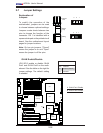
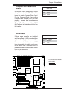
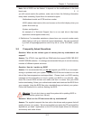
Parallel (Printer) Port
Connector
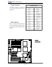
The parallel (printer) port is located
at J21. See the table on the right for
pin defi nitions.
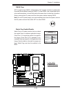
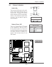
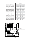
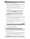
2-9 Parallel Port, Floppy Drive, Hard Disk Drive and
SIMLP IPMI Connections
Note the following when connecting the fl oppy and hard disk drive cables:
• The fl oppy disk drive cable has seven twisted wires.
• A red mark on a wire typically designates the location of pin 1.
• A single fl oppy disk drive ribbon cable has two connectors to provide for two
fl oppy disk drives. The connector with twisted wires always connects to drive
A, and the connector that does not have twisted wires always connects to drive
B.
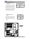
Parallel (Printer) Port Connector
Pin Defi nitions
Pin# Defi nition Pin # Defi nition
1 Strobe- 2 Auto Feed-
3 Data Bit 0 4 Error-
5 Data Bit 1 6 Init-
7 Data Bit 2 8 SLCT IN-
9 Data Bit 3 10 GND
11 Data Bit 4 12 GND
13 Data Bit 5 14 GND
15 Data Bit 6 16 GND
17 Data Bit 7 18 GND
19 ACK 20 GND
21 BUSY 22 Write Data
23 PE 24 Write Gate
25 SLCT 26 NC
A
A. Parallel Port