


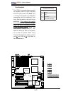
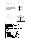
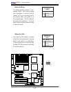
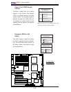
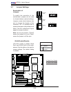
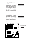

2-24
X7DA3+ User's Manual
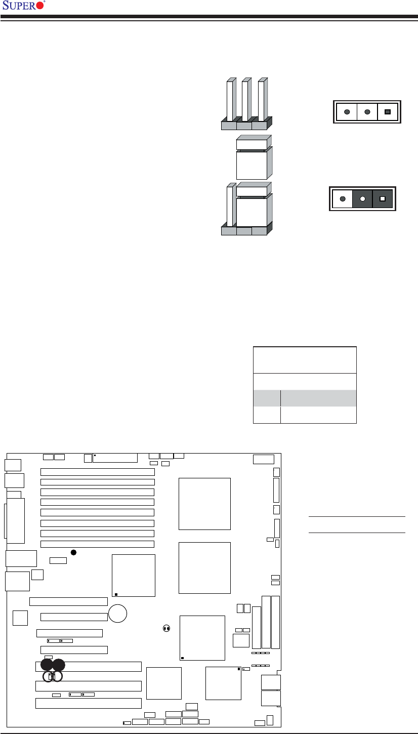
LAN1/2
®
JLAN1
S
UPER X7DA3+
Fan1
8-pin PWR
J
F
1
FP Control
SPK
PW LED
JOH1
Fan3
I
DE1
Floppy
Fan4
SA
TA
3
SA
TA5
USB4/
5
SM
B
P
CI-X
100 M
Hz Z
CR
(Green
S
lot
)
P
CI
-X
133
M
Hz
JWD
B
atter
y
G
LAN
C
T
LR
PCI-
Exp x4
North
Brid
g
e
COM1
Fan
6
Fan
5
AT
X PWR
4
-Pin
P
WR
J3P
Parrallel
Port
2
4
-Pin
SAS
Controller
P
X
H
CPU1
C
P
U
2
South
B
rid
ge
Fan
7
JAR
J17
PSF
JPW2
JPW1
JPW3
Fan
2
C
ompa
ct
Flash
L
E1
Fan8
J
C
F
1
JWF
1
SATA2
SATA4
SAT
A
1
SAT
A
0
JL
1
Slot
1
Slot
2
Slot
3
P
CI
-X
133 M
Hz
Slot
4
JPL2
Slot
5
PCI-33MHz
S
lot
6
PCI-Exp x16
SIM LP IPMI
Slot
7
D
IMM 1A (Ban
k
1)
DIMM 1B (Ban
k
1)
D
IMM 2A
(B
an
k
2)
DIMM 2
B
(B
ank
2
)
D
IMM 3A (B
ank 3)
DIMM 3B (Bank 3)
D
IMM 4A
(B
an
k 4
)
D
IMM
4B (Ban
k
4)
J
BT1
J
WOL
J
WOR
K
B/
M
ouse
U
SB 0
/
1
/2/3
HD
Audio
J
I
2
C2
J
I
2
C
3
J
I
2
C4
G
reencree
k
B
I
OS
CPU
Fan 1
CD1
JPL1
J
I
2
C1
CPU
Fan2
SG
P
IO1
SG
P
IO2
J
S1
0
SAS4-
7
SAS
0
-
3
JP
S
1
AC
T
0-3
ACT4-
7
Audio
CTRL
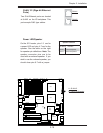
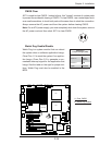
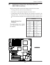
2-7 Jumper Settings
Explanation of
Jumpers
To modify the operation of the
motherboard, jumpers can be used
to choose between optional settings.
Jumpers create shorts between two
pins to change the function of the
connector. Pin 1 is identifi ed with a
square solder pad on the printed circuit
board. See the motherboard layout
pages for jumper locations.
Note: On two pin jumpers, "Closed"
means the jumper is on and "Open"
means the jumper is off the pins.
Connector
Pins
Jumper
Cap
Setting
Pin 1-2 short
3 2 1
3 2 1
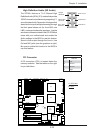
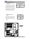
GLAN Enable/Disable
JPL1/JPL2 enable or disable GLAN
Port1 and GLAN Port2 on the moth-
erboard. See the table on the right for
jumper settings. The default setting
is enabled.
GLAN Enable
Pin# Defi nition
1-2 Enabled (default)
2-3 Disabled
A
A. GLAN Port1 Enable
B. GLAN Port2 Enable
B