


Chapter 2: Installation
2-15
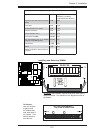
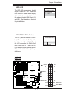
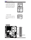
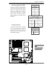
LAN1/2
®
JLAN1
S
UPER X7DA3+
Fan1
8-pin PWR
J
F
1
FP Control
SPK
PW LED
JOH1
Fan3
IDE1
Floppy
Fan4
SA
TA3
SATA5
USB4/
5
SMB
P
CI-X
100 M
Hz Z
CR
(Green S
lot)
P
CI
-X
133
M
Hz
JWD
B
atter
y
G
L
AN
C
TLR
PCI-
Exp x
4
North
Brid
g
e
COM1
Fan
6
Fan
5
A
T
X PWR
4
-Pin
P
WR
J3P
Parrallel
Port
2
4
-Pin
SAS
Controller
P
X
H
CPU1
CP
U
2
South
B
rid
ge
Fan
7
JAR
J17
PSF
JPW2
JPW1
JPW3
Fan
2
C
ompa
ct
Flash
LE1
Fan8
J
C
F1
JWF1
SATA2
SATA4
SA
TA
1
SA
TA
0
JL
1
Slot
1
Slot
2
Slot
3
P
CI-X
133 M
Hz
Slot
4
JPL2
Slot
5
PCI-33MHz
Slot
6
PCI-Exp x16
SIM LP IPMI
Slot
7
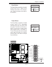
D
I
MM
1
A
(B
an
k 1
)
D
IMM
1B (Ban
k
1)
D
IMM 2A
(B
an
k 2
)
DIMM
2B
(Bank
2)
D
IMM 3A
(B
an
k
3)
DIMM 3B (Bank
3)
D
IMM 4
A
(B
ank 4)
D
I
MM
4B
(B
ank
4)
JBT1
J
WOL
J
WOR
KB/
M
ouse
USB
0
/
1/2/3
HD
Audio
J
I
2
C2
J
I
2
C3
J
I
2
C4
G
reencree
k
B
I
OS
CPU
Fan 1
CD1
JPL1
J
I
2
C1
CPU
Fan2
SG
P
IO1
SG
P
IO2
J
S1
0
SAS
4
-
7
SAS0-3
JP
S
1
AC
T
0-3
ACT4-
7
Audio
CTRL
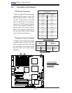
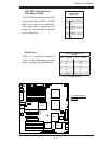
Universal Serial Bus (USB)
There are six USB 2.0 (Universal Se-
rial Bus) ports/headers on the mother-
board. Four of them are Back Panel
USB ports (USB#0/1/2/3: JUSB1),
and the other two are Front Panel
USB headers (USB#4/5:JUSB2).
See the tables on the right for pin
defi nitions.
Chassis Intrusion
A Chassis Intrusion header is located
at JL1 on the motherboard. Attach the
appropriate cable from the chassis to
inform you of a chassis intrusion when
the chassis is opened.
Chassis Intrusion
Pin Defi nitions (JL1)
Pin# Defi nition
1 Intrusion Input
2 Ground
A
B
C
A. Back panel USB Ports
01/2/3
B. Front Panel USB 4/5
C. Chassis Intrusion
Back Panel USB
(USB0/1/2/3)
Pin# Defi nitions
1 +5V
2 PO-
3PO+
4 Ground
5N/A
Front Panel USB
Pin Defi nitions (USB4)
USB4
Pin # Defi nition
USB5
Pin # Defi nition
1 +5V 1 +5V
2 PO- 2 PO-
3PO+ 3PO+
4 Ground 4 Ground
5 Key 5 No connection