D14324.04—DECEMBER 2009
82
Profile series with Codec C60
Administrator Guide
Contents Introduction Getting started About the menus The settings menu Settings Library Cameras Appendices Contact us
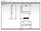
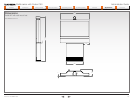
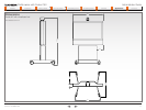
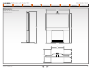
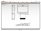
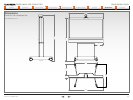
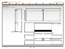
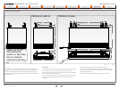
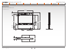
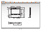
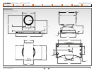
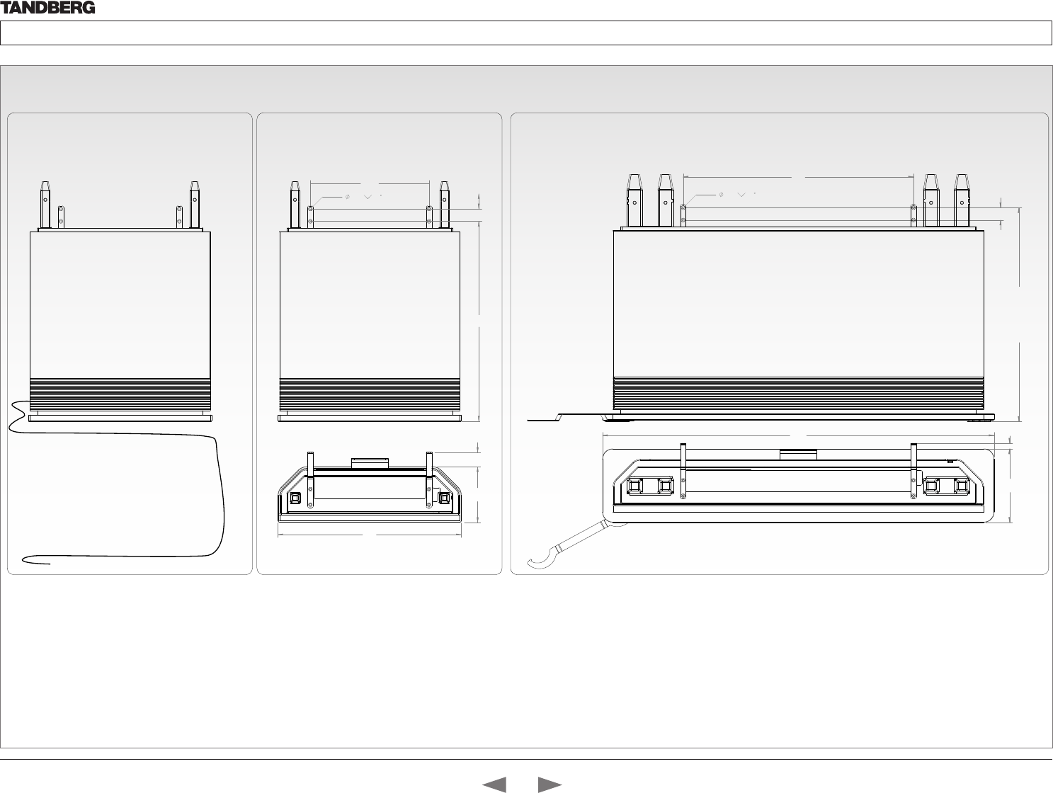
Profile wall mount setup
Telecom AS
746
692
(adjustable feets)
40
1268
238 18
7,0
90
PROFILE 52 DUAL
384
7,0
90
594
180 47
686
40
PROFILE 42 AND 52
Cables are by de-
fault exiting the
system on right side,
but can easily be
swithced to left side.
PROFILE -WALL MOUNT SETUP
WARNING!
Due to the size and mass of this equipment, it is very important that
the wall mount unit is safely installed according to the installation
instructions and that the wall is able to safely support the product.
It is highly recommended that the wall mounted system is installed by
trained personnel
Mounting
Use the Allen key, which is found in the foot box, when fastening the
wall brackets to the bottom module with four M6x10 screws
Place the bottom module by the wall, mark where to bolt the bracket
and move away the bottom module
NOTE! Use a level to make sure the system is mounted in an upright
position. Add a spacer between the wall bracket and the wall if
necessary.
Add the suitable fixing device for the screws in the wall
Open the rear door and locate and connect the cables which are
lead out of the system at the rear side (the door is not accessible
when placed by the wall)
Place the bottom module by the wall and bolt it to the wall.
Contents
Introduction
Getting started
About the menus
The Settings menu
The Settings library
Cameras
Appendices
Contact us
Appendices


