


Configuration Quick Reference A-25
Configuration
Quick-Reference
AT
*
MX13 =28.8 (V.34 modems only)
AT
*
MX14 =31.2 (V.34 modems only)
AT
*
MX15 =33.6 (V.34 modems only) (default)
Buffers
Buffer Option
Lets you specify whether normal or reduced size buffers store data received from a local DTE.
Use this parameter if you have DTE-to-DTE flow control enabled, to reduce the amount of data
sent to the remote DTE when a flow-off condition is received at the local DTE.
AT
*
NB0 =Regular Normal capacity buffers are used.
AT
*
NB1 =Reduced Reduced sized buffers are used allowing less data to accumulate in the modem.
When the SDC modem is operating in synchronous reliable mode, selecting
Buffers
=Reduced
reduces throughput delay while transmitting data.
Netwrk Comp
Network Compensation
Lets you enhance modem performance reliability when operating with network equipment.
AT
*
NC0 =Off Off should be selected when making most normal connections within a continent.
AT
*
NC1 =Lvl1 Select Lvl1 if the modem is experiencing performance problems when connected to a line
terminating equipment via a short loop, having low loop loss with below normal receive signal
levels (for example, when operating behind a low grade PBX). NOTE: This option limits the
maximum DCE data rate to 21,600 bps.
AT
*
NC2 =Lvl2 Lvl2 is recommended when performance problems are encountered making intercontinental
calls. NOTE: This selection limits the maximum DCE data rate to 19,200 bps.
When operating in an environment where the conditions described for Lvl1 and Lvl2 exist,
Lvl2 is recommended to enhance performance.
AT
*
ND
View Phone #
=n
View Stored Telephone Numbers
Lets you view the telephone numbers stored in the modem’s nine telephone book addresses.
Enter AT
*
ND<CR>
Ext Cntrl
External Control
Lets you select which pin the AT
*
OP (Ext Select) command responds to. NOTE: If AT
*
OP
is set to 0, this command has no effect.
AT
*
OC0 =Pin 14 Loads an option set based on the transition of Pin 14. This setting overrides the AT
*
RE
(Restore) command setting FP/116 or FP/116.ACU.
AT
*
OC1 =Pin 20 Loads an option set based on the transition of Pin 20. When using this setting, set the AT&D
(DTR) command to High. This setting overrides the AT
*
RE (Restore) command settings FP/
108.1 and FP/108.ACU and all AT&D (DTR) command settings except High.
Ext Select
External Option Set Select (also known as 116 Select)
Controls how the modem uses an external pin to select option sets. The pin used is defined by
the AT
*
OC (Ext Cntrl) command.
AT
*
OP0 =Off The AT
*
OP command is disabled.
AT
*
OP1 =1H/2L There are 12 settings with the format
n
H-
m
L, where
n
=1, 2, 3, or 4, and
m
=1, 2, 3, or 4. When
the pin specified by the Ext Cntrl option (14 or 20) transitions from low to high, the modem
loads the “H” option set. When the pin specified by the Ext Cntrl option (14 or 20) transitions
from high to low, the modem loads the “L” option set.
AT
*
OP2 =1H/3L
AT
*
OP3 =1H/4L
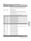
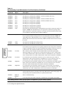
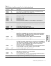
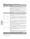
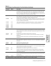
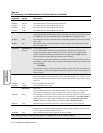
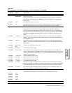
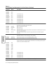
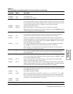
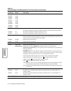
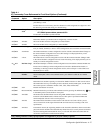
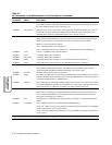
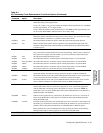
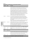
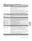
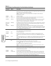
Table A-1.
AT Commands, Cross-Referenced to Front Panel Options (Continued)
AT
Command
Parameter &
Option Description
Gray shading indicates country-specific options. See Appendix C for your country’s options.