


B-6 Cabling and Interface Pinouts
Interface
Pinouts
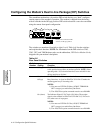
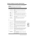
Differences, EIA/TIA 232-D and ITU Rate V.35 Interfaces
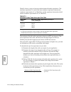
There are some differences in how your modem operates when using EIA/TIA
232-D and ITU Rate V.35 electrical interfaces. These differences, and settings
to use when operating with a V.35 interface, are as follows.
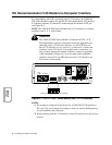
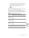
DIAL LINE, LEASE (PRIVATE) LINE, PHONE Connector Pinouts
DIAL LINE, LEASE (PRIVATE) LINE, and PHONE connector pinouts vary by
country. Consult Appendix C for your country's pinouts.
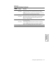
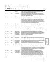
21 Loop 2 Control Signal initiated at local terminal and passed to local modem,
causing it to initiate remote digital loopback test (V.54 Loop 2).
22 Ring Indicator (RI) Passed from local modem to local terminal. On during ringing,
off between rings and when no ring received.
23 External Transmit
Clock (B)
Transmit timing signal generated by some synchronous DTEs,
providing clock to the local modem.
24 External Transmit
Clock (A)
Transmit timing signal generated by some synchronous DTEs,
providing clock to the local modem.
25 Test Indicate (TI) Local modem signals to local terminal when local modem is in
test. The terminal can initiate a Busy Out condition on this
circuit.
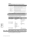
When a V.35 Electrical
Interface is Selected...
The Following Options
Cannot Be Selected... Set:
Pin 11 is not supported. Mode=External
(AT
*
CA2)
Mode=
Originate (AT
*
CA0)
Answer (AT
*
CA1), or
Auto (AT
*
CA3)
Pin 12 is not supported —NA——NA—
Pin 13 is not supported —NA——NA—
Pin 14 is not supported Ext Cntrl=Pin 14
(AT
*
OC0)
Ext Cntrl=Pin 20
(AT
*
OC1—default).
Restore=FP/116
(AT
*
RE3)
Restore=FP/116.ACU
(AT
*
RE6)
—NA—
Pin 16 is not supported —NA——NA—
Pin 23 is not supported —NA— Switch S1 on modem rear
panel to the Off (up) position.
Table B-2.
ITU V.35 Modem/Computer Interface Connections (Continued)
Pin V.35 Signal Definition