


Installing the Modem 2-13
Installing
the Modem
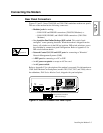
Connecting the Modem to a Network Management System
326X Series Modems can be connected to the following Telenetics systems:
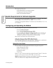
• 9110 NMS (Figure 2-9)
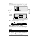
• 9000-PC (Figure 2-10)
• 9000-UX(Figure 2-10)
Use the modem’s NC IN and NC OUT 8-pin DIN connectors for NMS connections.
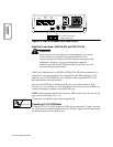
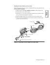
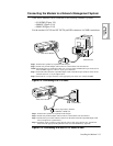
Figure 2-9. Connecting to a 9110 NMS
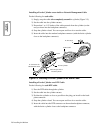
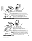
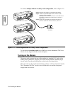
Figure 2-10. Connecting to a 9000-PC or 9000-UX NMS
326X Series Modem
9110 Terminal
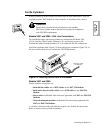
Step 1
: Install ferrite cylinders as explained in this chapter.
Step 2: Attach an 8-pin DIN adapter cable connector to the modem’s NC IN connector.
NOTE
: The modem can be connected to either a 9- or 25-pin serial communication port on the rear of
the 9110 DMS. Figure 2-7 shows a 25-pin port connection.
Step 3
: Attach the other end of the 8-pin DIN adapter cable to the DB 25-pin connector on the 9110’s
network control 9- or 25-pin adapter cable.
Step 4: Attach the 25- or 9-pin connector to the appropriate port on the rear of the 9110 DMS.
1
2
3
Junction Box
326X Series Modem
Step 1: Install ferrite cylinders as explained in this chapter.
Step 2: Attach an 8-pin DIN adapter cable connector to the modem’s NC IN connector.
Step 3: Connect the 8-pin control-channel connector on the other end of the 8-pin DIN adapter cable
into its receptacle on a junction box.
Step 4: Attach the 50-pin connector on the network control cable to the junction box. Connect the
other end to the appropriate Digi-Board on the rear of the NMS Proxy Agent PC.
To Proxy Agent (PC), and then
to 9000-PC or 9000-UX
1
2
3