2-6 Installing the Modem
Installing
the Modem
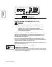
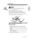
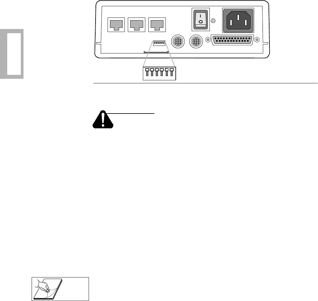
Figure 2-3. 3261/3266 Modem Rear Panel Layout
Electrical Interfaces—EIA/TIA-232 and ITU-TS V.35
Caution
Ensure that the electrical interfaces of the equipment you connect
to the modem are compatible. Incompatible interfaces may
seriously damage the modem. Telenetics makes no guarantee of the
equipment’s integrity if you do not ensure that compatible
interfaces are used. If your DTE has a different interface, you will
need an external converter cable.
326X Series Modems have an EIA/TIA-232/EIA/TIA-562 electrical interface for
connection to external equipment. For compatibility with DTEs that have a V.35
interface, the V.34-SDC Modem is also available with the optional ITU-TS V.35
Recommendation electrical interface.
The rear-panel DTE port is configured at the factory for either interface. Both
interfaces are not available in a unit. Regardless of the interface, external DTEs are
connected through the modem’s rear-panel DTE port.
NOTE: When operating with the V.35 interface, DIP switch S1 must be set to the off
(up) position (see Figure 2-2 or 2-3).
To purchase a compatible cable, consult Appendi xB.
Operating at V.34 DTE Rates
To operate V.34 or V.34-SDC modems at DTE rates greater than 19.2 kbps, you must
use cables that can handle the higher data rates. Refer to Appendix B for instructions
on determining the correct cables to use.
PHONE
DIAL
LINE
OUT IN
NC
DTE
1 ON 6
1 2 3 4 5 6
123456
LEASE
LINE
Factory Preset 6-Position
DIPs are Off (Up)
Appendix B


