Cabling and Interface Pinouts B-11
Interface
Pinouts
5) If the transmitted and received messages are different (i.e., character or
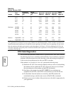
framing errors), verify the cable length to the limit specified in Table B-4.
Reduce the cable length or capacitance of the cable to the theoretical limit and
retry the steps listed in this section. (If the same cable length is required, it is
recommended that a low capacitance type cable be used.)
If the modem is installed at a host site, perform the following steps:
1) Set the Mode option AT
*
SM (EC/DC OPT'S category) to Reliable. (Reliable
mode ensures data is transmitted during this test.) NOTE: Do not initiate loop
tests while performing the diagnostic procedures in this section.
2) Follow Steps 1 to 3 in the section above to verify the cable at a remote site.
3) Once the cable at the remote site has been verified, initiate a dial connection
with the host site.
4) If there are no errors in data transmission, the cable at the host site is most
likely appropriate for the application.
5) If the transmitted and received messages are different, the cable at the host site
is most likely incorrect for the application. Verify the cable length to the limit
specified in Table B-4. Reduce the cable length or capacitance of the cable to
the theoretical limit and retry Steps 1 to 3 in the section above. (If the same
cable length is required, it is recommended that a low capacitance type cable
be used.)
NOTE: These tests should be done prior to a Local Analog Loopback (LAL) or
Remote Digital Loopback (RDL) test when troubleshooting.


