


Configuration Quick Reference A-11
Configuration
Quick-Reference
AT&I3 Modem ID# 1 Product code
AT&I4 Modem ID# 1 Network control address (optional)
AT&I5 Modem ID# 1 Device serial number
AT & J 0/
AT & J 1
Telc o
=RJ11C
Dial Line Jack Type
This 6-pin modular jack type is the most common permissive data mode (voice) jack
arrangement found in the home or office and operates on a single-line bridged tip-and-ring
voice or low-speed data application service.
AT & J 2 =RJ45S This 8-pin modular jack type is the most common programmable jack arrangement and permits
the use of an exclusion key telephone. This jack also operates on a single-line bridged tip-and-
ring voice or low-speed data application service.
NOTE: When installing the modem in a PBX environment, the interface to the PBX should be
a voice grade jack (RJ11). Although an RJ11 jack is installed, Telenetics recommends that
Telco=RJ45S. This optimizes modem performance the when operating at high
data rates over a
PBX. In a normal Telco-supplied loop situation, the telco options setting should match the jack
type installed.
AT & J 3 =RJ16CS This 6-pin modular jack type is a special permissive data mode jack arrangement that allows
use of an exclusion key telephone.
AT & J 4 =RJ4MB This 8-pin modular programmable data mode jack arrangement supports Make Busy operation.
Using this jack type, you can make the modem appear to be off-hook to the central telephone
office. Note: In modems in the U. S. A. and Canada, the Make Busy function operates only in
nest card modems. (Make Busy settings display in standalone modems, but are not active.)
AT & L0
Line
=Dial
Line Type
The modem communicates over dial lines in dial applications only.
AT&L1 =2W Lease The modem communicates over a 2-wire leased line. The ACUs (AT and V.25bis) are not
functional when the modem is connected to a leased line.
AT&L2 =4W Lease The modem communicates over a 4-wire leased line. The ACUs (AT and V.25bis) are not
functional when the modem is connected to a leased line.
AT & M0
AT Form
=Async
AT Data Format
Determines the format of the data when ACU Select is set to AT.
The modem communicates asynchronously in command and data mode.
AT&M1 =Sync Data The modem communicates asynchronously when in command mode (disconnected from the
dial line), and synchronously when in data mode.
AT&M2 =DTR Dial When an off-to-on DTR transition is detected, the modem dials the number stored in the
memory location designated by the Default Dial option. Once connected, the modems transmit
data synchronously. If DTR transitions from on-to-off, the modem hangs up and returns to the
asynchronous command mode.
AT&M3 =Man Dial DTR signals toggle between talk and data mode. With DTR off, numbers can be dialed from a
telephone. Once an answer tone is heard, the telephone is hung up, and DTR is raised; the
modems connect and send data sychronously.
AT & P0
Pulse Cycle
=40%
Pulse Cycle
The make/break ratio is 40:60.
AT & P1 =33% The make/break ratio is 33.5:66.5.
AT & P2 =38% The make/break ratio is 38.5:61.5.
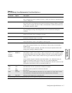
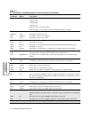
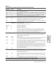
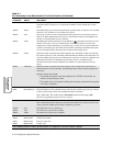
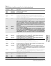
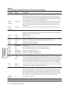
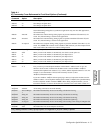
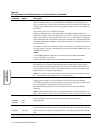
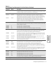
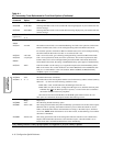
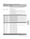
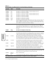
Table A-1.
AT Commands, Cross-Referenced to Front Panel Options (Continued)
AT
Command
Parameter &
Option Description
Gray shading indicates country-specific options. See Appendix C for your country’s options.