


Country-Specific Information C-39
Country-Specific
Information
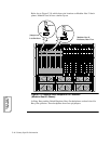
Rear Panel Pinouts
This section provides modem rear panel pinouts, cross-referenced to the pinouts for
the telco jacks supported in the U. S. A.
3260 Modem
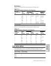
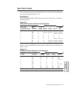
Table C-16 describes DIAL LINE connector pinouts for RJ jack types. X indicates
the signal is active.
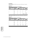
Table C-17 describes PHONE connector pinouts for RJ jack types. X indicates the
signal is active.
Table C-16.
DIALLINE Connector Pinouts for Jack Operation
DIAL LINE
Connector Pin No.
DIAL Line
Jack
Function
TELCO Jack Selection
RJ4MB RJ45S RJ16C RJ11C
Leased
Line
1 MB X Not Used Not Used Not Used Not Used
2 MB1 X Not Used Not Used Not Used Not Used
3 MI XXXNot UsedNot Used
4 RingXXXXX
5 Tip XXXXX
6 MIC XXXNot UsedNot Used
7 PR X X Not Used Not Used Not Used
8 PC X X Not Used Not Used Not Used
Table C-17.
PHONE Connector Pinouts for Jack Operation
PHONE Connector
Pin No.
PHONE Jack
Function
TELCO Jack Selection
RJ4MB RJ45S RJ16C RJ11C
1 N/C N/C N/C N/C N/C
2 N/C N/C N/C N/C N/C
3 MI X X X Not Used
4RingXXXX
5 Tip XXXX
6 MIC XXXNot Used
7 N/C N/C N/C N/C N/C
8 N/C N/C N/C N/C N/C
N/C = Not Connected