


A-22 Configuration Quick Reference
Configuration
Quick-Reference
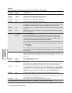
AT
*
LE1 =15 min The modem returns to the leased line after 15 minutes.
AT
*
LE2 =30 min The modem returns to the leased line after 30 minutes.
AT
*
LE3 =1 Hr The modem returns to the leased line after 1 hour.
AT
*
LE4 =2 Hr The modem returns to the leased line after 2 hours.
AT
*
LE5 =4 Hr The modem returns to the leased line after 4 hours.
LAL Busy Out
Local Analog Loopback Test Busy Out
Determines whether the modem appears busy to incoming calls during a local analog loopback
test.
NOTE:
Set AT&J (TELCO OPT’S Telco) to RJ4MB before enabling this option.
AT
*
LL0 =Off The modem does not busy out the line during a local analog loopback test, allowing incoming
calls to ring.
AT
*
LLl =On The modem connects to the line during a local analog loopback test, making the line appear
busy to incoming calls.
AT
*
LNm,n
Link Phone #’s:
#m to #n
Link Telephone Numbers
Lets you link telephone numbers stored in the modem’s telephone book. Some remote
locations provide more than one number to call in case one is busy. If a call fails and the
number is linked, the modem pauses and then calls the linked number. NOTE: With this
feature enabled, the modem dials linked numbers before redialing.
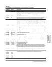
To link numbers using the AT Command, enter AT
*
LN, followed by the memory location of
the number you want to link from (n), a comma, and the memory location of the number to link
(m). For example:
AT
*
LN2,4
In this example, memory location 2 is linked to memory location 4. T oclear the link between
the two memory locations, enter AT
*
LN2. Effectively, memory location 2 is now linked to no
memory location.
Low Speed
Low Speed
Determines which low-speed modulation mode is used when a higher (V.34, V.32bis, V.32, or
V.22bis) modulation mode connection cannot be made while Mod=V.34 Auto, V32bis Auto or
Auto V32.
AT
*
LS0 =Bell Bell 103 modulation mode is used.
AT
*
LS1 =CCITT V.21 modulation mode is used.
DTE Pin 25
DTE Pin 25
Controls whether the modem uses EIA/TIA 232-D Pin 25 as an input or an output. Set rear
panel Switch 2 to match this setting (see Table A-6 for details on rear panel switches).
AT
*
LT0 =Busy The DTE signals the modem on Pin 25 to make the modem appear busy to incoming calls. Set
rear panel DIP switch 2 to the off (up) position. Also, set AT&J (Telco) to RJ4MB. NOTE: In
modems in the U. S. A. and Canada, the Make Busy function operates only in nest card
modems. (Make Busy settings display in standalone modems, but are not active.)
AT
*
LTl =Test The modem signals the DTE on V.24 Circuit 142 (Pin 25) when a test is in progress.
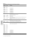
PSTN Signaling
PSTN Signaling
Determines how the modem handles disconnect signaling when operating in the V.34, V.32bis
or V.32 (coded or uncoded) modulation modes.
AT
*
MD0 =Off Your modem disconnects without signaling the remote modem.
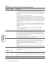
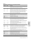
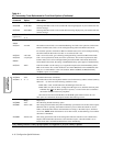
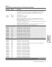
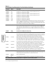
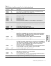
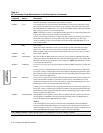
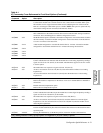
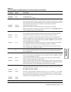
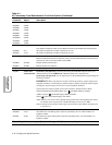
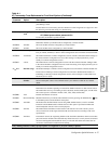
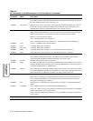
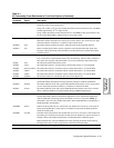
Table A-1.
AT Commands, Cross-Referenced to Front Panel Options (Continued)
AT
Command
Parameter &
Option Description
Gray shading indicates country-specific options. See Appendix C for your country’s options.