


Design Considerations for In-Circuit Programming
3-2
3.1 Bootstrap Loader
The JTAG pins provide access to the Flash memory of the MSP430F device.
On some devices, these pins must be “shared” with the device port pins, and
this sharing of pins can complicate a design (or it may simply not be possible to
do so). As an alternative to using the JTAG pins, MSP430F devices contain a
program (a “Bootstrap Loader”) that permits the Flash memory to be erased
and programmed simply, using a reduced set of signals. Application Notes
SLAA089 and SLAA096 fully describe this interface. TI does not produce a BSL
tool. However, customers can easily develop their own BSL tools using the
information in the Application Notes, or BSL tools can be purchased from 3
rd
parties. Refer to the MSP430 web site for the Application Notes and a list of
MSP430 3
rd
party tool developers.
Texas Instruments suggests that MSP430Fxxx customers design their circuits
with the BSL in mind (i.e., we suggest providing access to these signals, e.g.
via a header). Refer to section Device Signals below.
Refer to FAQ, Hardware #9) for a second alternative to sharing the JTAG and
port pins.
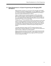
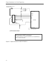
3.2 External Power
The PC parallel port can source a limited amount of current. Owing to the ultra
low power requirement of the MSP430, a stand-alone FET does not exceed the
available current. However, if additional circuitry is added to the tool, this
current limit could be exceeded. In this case, external power can be supplied to
the tool via connections provided on the MSP-FET430X110 and the Target
Socket modules. Refer to the schematics and pictorials of the MSP-
FET430X110 and the Target Socket modules presented in Appendix B to locate
the external power connectors.
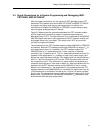
The USB-IF can supply targets with up to 100mA through pin 2 of the 14-pin
connector. Vcc for the target can be selected between 1.8V and 5.0V in steps
of 0.1V. Alternatively the target can be supplied externally. Then the external
voltage should be connected to pin 4 of the 14-pin connector. The USB-IF then
adjusts the level of the JTAG signals to external Vcc automatically. Only pin 2
(USB-IF supplies target) OR pin 4 (target is externally supplied) should be
connected, not both at the same time.
To connect 20-pin MSP430 devices to the USB-IF, the 28pin socket module
MSP-TS430DW28, which is part of the MSP-FET430P120-kit, should be used.
Pin 1 of the 20-pin device should align with pin 1 of the 28-pin socket.
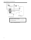
When an MSP-FET430X110 is powered from an external supply, an on-board
device regulates the external voltage to the level required by the MSP430.
When a Target Socket module is powered from an external supply, the external
supply powers the device on the Target Socket module and any user circuitry
connected to the Target Socket module, and the FET Interface module
continues to be powered from the PC via the parallel port. If the externally
supplied voltage differs from that of the FET Interface module, the Target
Socket module must be modified so that the externally supplied voltage is
routed to the FET Interface module (so that it may adjust its output voltage