


Design Considerations for In-Circuit Programming
3-5
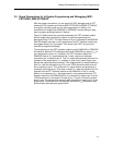
3.4 Signal Connections for In-System Programming and Debugging, MSP-
FET430X110
With the proper connections, you can use the C-SPY debugger and the MSP-
FET430X110 to program and debug code on your own target board. In addition,
the connections will support the GANG430 and PRGS430, thus providing an
easy way to program prototype boards, if desired.
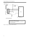
Figure 3-1 below shows the connections between the FET and the target
device required to support in-system programming and debugging using C-
SPY. If your target board has its own local power supply, such as a battery, do
not connect Vcc to pin 2 of the JTAG header. Otherwise, contention may occur
between the FET and your local power supply.
The figure shows a 14-pin header being used for the connections on your target
board. It is recommended that you build a wiring harness from the FET with a
connector which mates to the 14-pin header, and mount the 14-pin header on
your target board. This will allow you to unplug your target board from the FET
as well as use the GANG430 or PRGS430 to program prototype boards, if
desired.
The signals required are routed on the FET to header locations for easy
access. Refer to the device datasheet (for pin numbers) and the schematic and
PCB information in Appendix B to locate the signals.
After you make the connections from the FET to your target board, remove the
MSP430 device from the socket on the FET so that it does not conflict with the
MSP430 device in your target board. Now simply use C-SPY as you would
normally to program and debug.