


8900NET Instruction Manual 11
Installation
Cabling
This section describes physical connections, the connectors and cables,
used for network communications. Setup procedures for each type of con-
nection are described in
Establishing Frame Network Identity
on page 19.
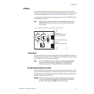
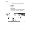
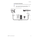
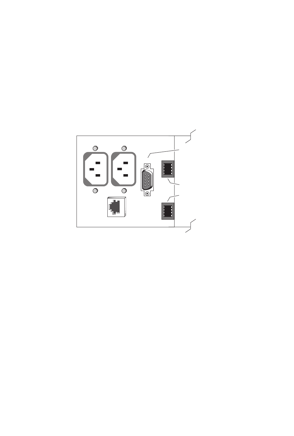
An example of control and monitoring connectors on the 8900TFN frame
are illustrated in Figure 5.
Note
There are several versions of frames in the Gecko 8900 Series. Refer to the
8900 Series Frames manual that came with your frame for the latest informa-
tion on cabling.
Figure 5. 8900NET Input/Output Connectors on 8900TFN Frame
Frame Alarm
The Frame Alarm is accessed through pins 8 and 9 of the RS-232 connector.
Details for connecting an external customer-supplied alarm are given in the
Gecko 8900 Series Frames Instruction Manual
.
Note
Earlier version 8900 frames used a BNC connector labelled SMPTE ALARM
to access the alarm connection. For information concerning the SMPTE
Alarm bus cable, refer to the
Gecko 8900 Frames Instruction Manual
.
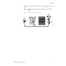
RS-232 Communication Port Cable
The nine-pin RS-232 connector is used to connect the frame to a PC to ini-
tially set the frame’s network communication parameters. After network
communication is established, subsequent changes to these parameters can
be made using the network GUI.
CAUTION
The RS-232 cable should be removed after completing the initial frame setup.
Leaving a long serial cable connected to the frame without a connection at
the other end may freeze the 8900NET module startup routine.
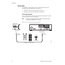
J1 J2
RS232
ETHERNET
Frame Alarm
(Video – J102 pins 8 and 9)
(Audio – J7 pins 8 and 9)
Network configuration storage
Frame ID
(Frame MAC address storage)
0612_31