


8900NET Instruction Manual 9
Installation
Installation
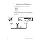
This section describes placing the module in the Gecko 8900 frame and
cabling the communications ports. Procedures for power-up, DIP switch
settings, and network configuration of the module are described in fol-
lowing sections.
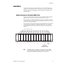
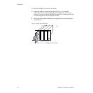
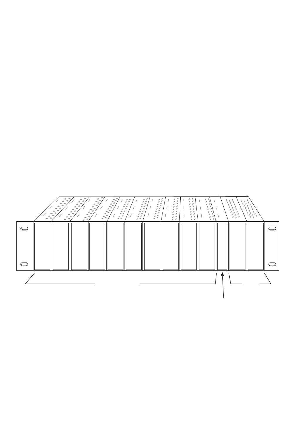
Module Placement in the Gecko 8900 Frame
There are ten cell locations in the frame to accommodate either analog or
digital modules. These are the left ten locations. Refer to Figure 3.
The two cells on the right are allocated for the power supplies. For addi-
tional information concerning the Power Supply module, refer to the
8900
Series Frames Instruction Manual
.
The third cell from the right is allocated for the 8900NET Network Interface
or Frame Monitor module. For additional information concerning the
Frame Monitor module, refer to the
Gecko 8900 Series Frames Instruction
Manual
.
Figure 3. 8900 Series Frame
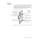
Note
The 8900NET module can be plugged in and removed from a Gecko 8900
Series frame with power on. When power is applied to the module, LED indi-
cators reflect the initialization process (see
Power Up
on page 16).
Frame Monitor
or 8900NET Network
Interface Module
(
only
)
Any 8900 Module
Power
Supplies
(only)
0612-04r1