


18 8900NET Instruction Manual
Enabling Alarms and Fan Speed Control Option
Enabling Alarms and Fan Speed Control Option
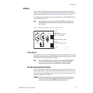
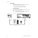
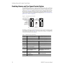
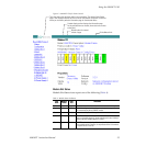
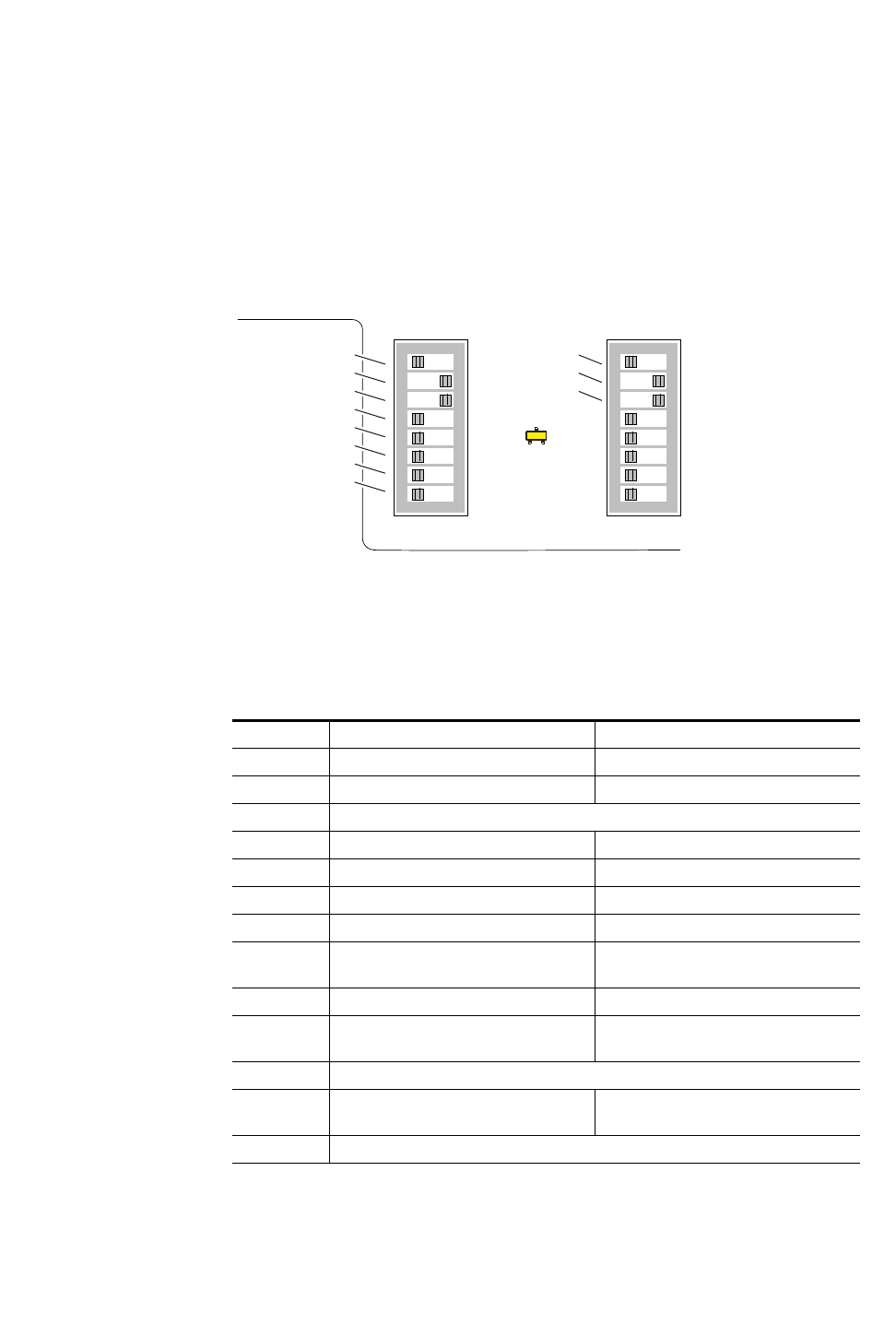
The 8900NET module has two eight-position DIP switches (S1 and S2) that
enable or disable the fault reporting functions and the variable fan speed
option (see Figure 11). Enabled fault alarms drive on-board LEDs and can
also be sent to SNMP monitoring stations when the SNMP network and
Agent software has been installed and configured (see
Network Module Con-
figuration for SNMP
on page 30).
Figure 11. Alarm Reporting DIP switches
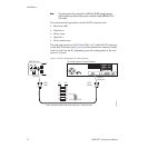
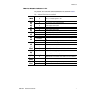
Disabling (or filtering) specific fault alarms can be useful in isolating prob-
lems in the frame. Refer to Table 2 for the possible settings. A settings table
is also silk-screened on the module.
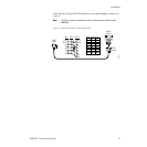
Table 2. Configuration DIP Switch Settings
S1 Segment Left Position (open) Right Position (closed)
1 PS1 Fault Reporting Enabled PS1 Fault Reporting Disabled
2 PS2 Fault Reporting Enabled PS2 Fault Reporting Disabled
3 (Not used) Over Temp reporting is always enabled locally and through SNMP
4 Fan Fault Reporting Enabled Fan Fault Reporting Disabled
5 Module Fault Reporting Enabled Module Fault Reporting Disabled
6 Frame Bus Error Reporting Enabled Frame Bus Error Reporting Disabled
7 Fan Speed Controlled by Temperature Fan Speed Fixed at Maximum
8
Network Module Control Enabled (remote
control via GUI is enabled)
Network Module GUI is placed in read only
mode
S2 Segment Left Position (open) Right Position (closed)
1
Status Enabled (enabled alarms are
reported over SNMP)
SNMP Reporting is disabled except for
Over Temp alarm
2 IP Address (not currently supported)
3
Frame Control Enabled (remote control via
GUI is enabled)
GUI for the frame and all modules within is
placed in read only mode
4 – 8 (Currently Not Used)
12345678
12345678
S2S1
Power Supply #1
Power Supply #2
Temperature
Fan
Module
Frame Bus
Fan Speed
NM Control
Status
8900NET
IP Address
Frame Control
Remote
Override
LED