


16 8900NET Instruction Manual
Power Up
Power Up
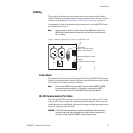
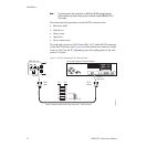
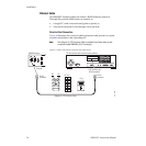
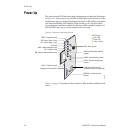
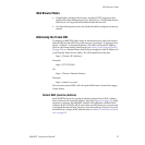
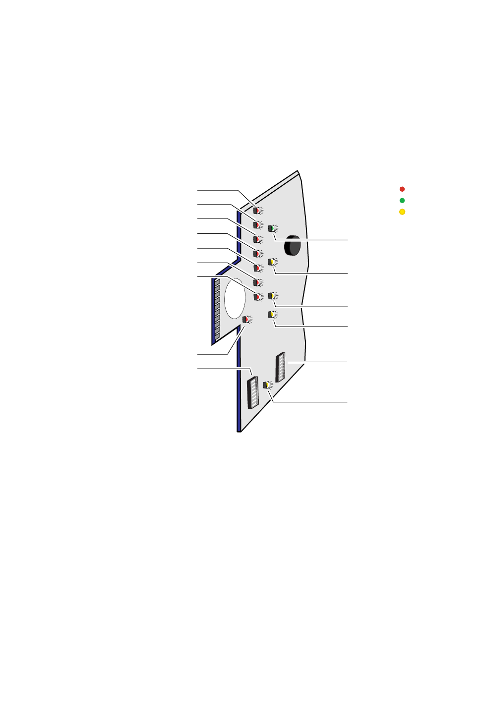
The various front LED indicators and configuration switches are illustrated
in Figure 10. Upon power-up, all LEDs should light for the duration of the
initialization process. After initialization the Power LED will be on and the
red Network Module LED (labeled NM) should go off. All other LEDs
report detected conditions within the frame and the installed modules. If
the NM LED does not go off, the board needs servicing.
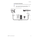
Figure 10. LEDs and Configuration Switches
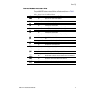
Table 1 on page 17 describes all the module’s LEDs and the conditions indi-
cated.
FAN (red)
MOD - Module Health Bus (red)
PS1 - Power Supply 1 (red)
PS2- Power Supply 2 (red)
TEMP - Temperature (red)
S1
8
7
6543
2
1
8
7
6
5
4
3
2
1
PWR - Power (green)
Red = Fault
Green = OK
Yellow = Active
LED Color Key
NM - Network Interface Module (red)
FB - Frame Bus (red)
COMM - Communication (yellow)
ETHER - Ethernet communiction
(yellow)
REM OVR - Remote Override
(yellow)
FAULT - Frame Fault (red)
INHIB - Module Health Inhibited
(yellow)
Configuration DIP switch S1
0612 -06
Configuration DIP switch S2
(functions currently not supported)