


8900NET Instruction Manual 17
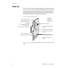
Power Up
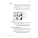
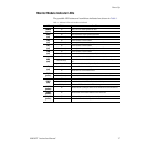
Monitor Module Indicator LEDs
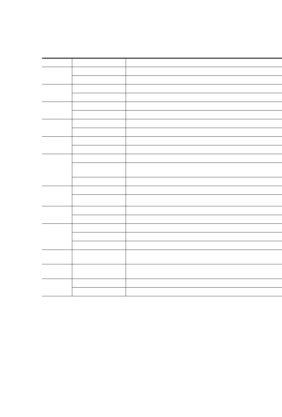
The possible LED status and conditions indicated are shown in Table 1.
Table 1. Indicator LEDs and Conditions Indicated
LED LED State Condition
POWER
(green)
Off Power is off or on-board regulator has failed
On continuously Module is powered
TEMP
(red)
Off Frame temperature is within specified parameters
On continuously Over-temperature condition detected in frame
PS2
(red)
Off Normal operation or alarm disabled
On continuously Power supply 2 is present and reporting an alarm condition
PS1
(red)
Off Normal operation or alarm disabled
On continuously Power supply 1 is present and reporting an alarm condition
FAN
(red)
Off Normal operation or alarm disabled
On continuously One or more fans in the front cover assembly is not rotating
MOD
(red)
Off Normal operation or alarm disabled
On continuously
Module health bus is not disabled and one or more modules is reporting an internal
fault
Long continuous flashing One or more modules is reporting a configuration error
FB
(red)
Off Network module is communicating with modules on the frame bus
On Internal frame bus communication failure
INHIB
(yellow)
Off Normal operation or alarm disabled
On continuously A non-compliant module in the frame has disabled the module health bus
FAULT
(red)
Off Normal operation
On continuously One of the on-board fault LEDs is illuminated or flashing
Flashing Indicates the MOD (module health LED) is flashing
COMM
(yellow)
On Indicates module is polling the devices on the internal frame communication bus
ETHER
(yellow)
On Indicates active communication detected on the Ethernet bus
REM OVR
(yellow)
Off All fault reporting is controlled by onboard configuration switches
On Software overrides onboard configuration switches