


4/00, TecraToshiba TRR Page 22
Tecra 750 Series Disassembly Overview, (cont.)
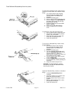
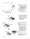
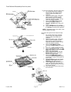
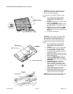
To remove the fan, follow the steps below.
1. Turn off the power to the computer.
Disconnect the AC adapter and all
external cables connected to the
computer.
2. Remove the battery pack, HDD pack,
optional memory module, modem
board, backup and RTC batteries,
keyboard, membrane switch, top cover
with display assembly, and system
board.
3. Turn the system board upside down
and remove the tape securing the fan
cable.
4. Disconnect the fan cable from PJ550
on the system board.
5. Turn the system board right side up and
remove two M2.5x4 screws.
6. Lift out the fan.
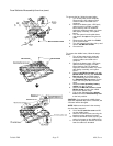
To remove the middle frame, follow the steps
below.
1. Turn off the power to the computer.
Disconnect the AC adapter and all
external cables connected to the
computer.
2. Remove the battery pack, HDD pack,
optional memory module, modem
board, backup and RTC batteries,
keyboard, membrane switch, top cover
with display assembly, and system
board.
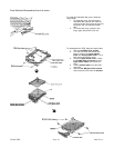
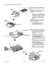
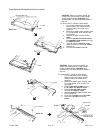
3. Remove two M2.5x4 screws and one
M2.5x8 screw securing the Selectable
Bay top cover to the middle frame.
4. Two positioning pins fit into holes on
the Selectable Bay top cover. Pry the
cover free of the pins then lift off the
cover.
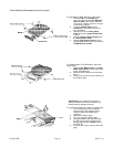
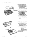
5. Disconnect two secondary battery
cables from the I/O board.
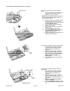
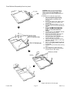
6. Remove six M2.5x8 screws and one
M2.5x4 screw securing the middle
frame to the bottom cover.
7. Pull out the Selectable Bay release
lever and set the Selectable Bay lock
to the lock position.
CAUTION: If you remove the middle frame
while the Selectable Bay lock is unlocked, the
I/O board will be damaged.
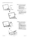
NOTE: Make sure the screw in the memory
slot has been removed.
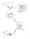
8. Lift off the PC card slot cover and lift
out the middle frame.
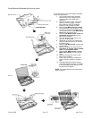
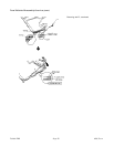
9. Remove one M2x3 screw securing the
bracket over the probe pin harness.
10. Remove two M2x5 screws securing the
probe pin harness to the middle frame.
11. Lift out the probe pin harness and note
how the cables are threaded.
ê