


4 Replacement Procedures
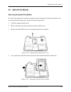
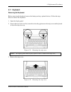
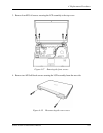
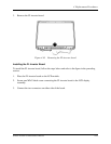
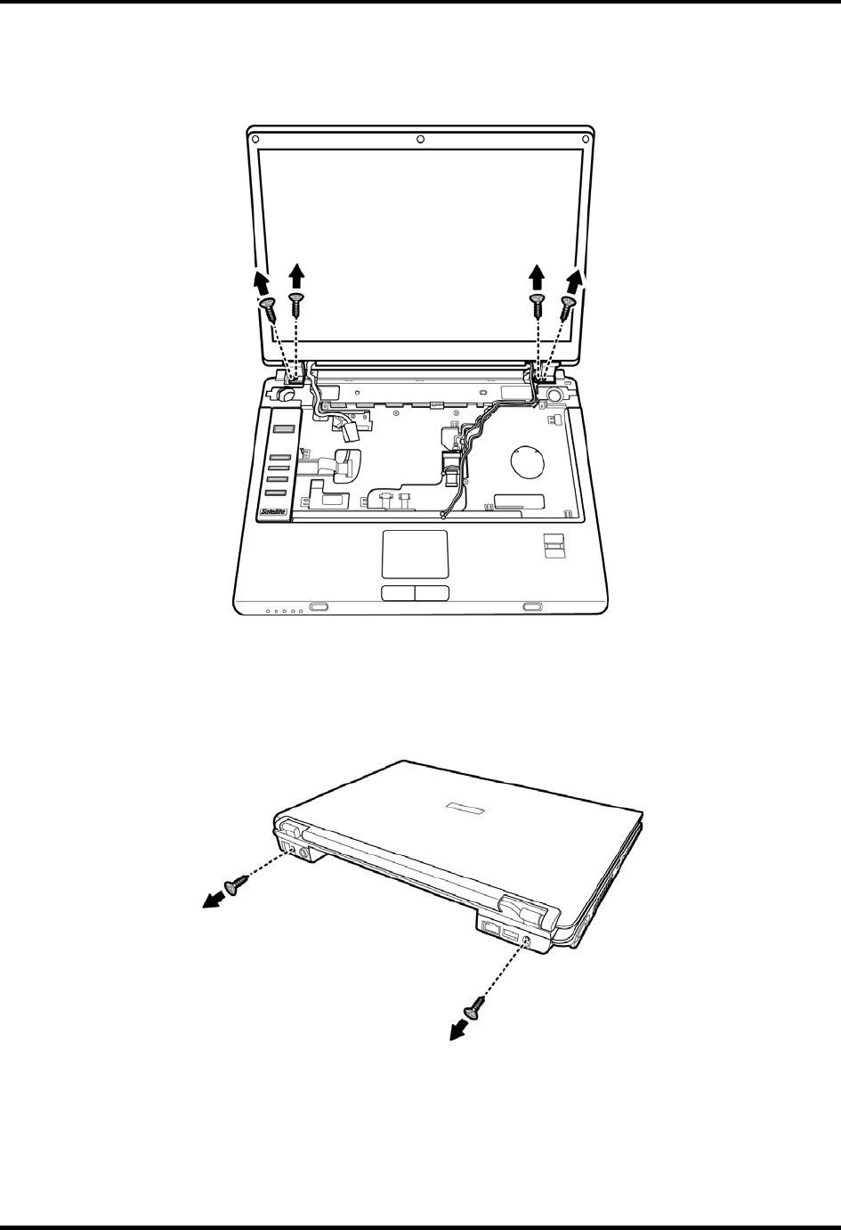
3. Remove four M2.5x8 screws securing the LCD assembly to the top cover
Figure 4-37 Removing the front screws
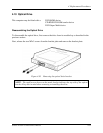
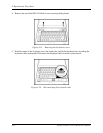
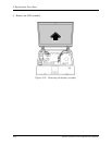
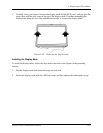
4. Remove two M2.5x8 black screws securing the LCD assembly from the rear side.
Figure 4-38 Disconnecting the rear screws
Satellite A130/ A135 Maintenance Manual 4-35