4 Replacement Procedures
4.24 System Board
Removing the System Board
To remove the system board, first remove the display assembly, keyboard, and top cover, and
then follow the steps below:
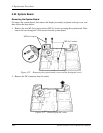
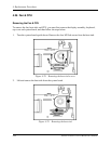
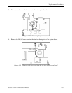
1. Remove the two M2.5x6 screws and two M2.5x3 screws securing the system board. Then
remove the two hexagonal VGA screws from the system board.
M2.5x 6 screws
M2.5x 3 screws
Figure 4-72 Removing the system board screws and the hexagonal screw
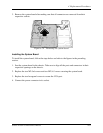
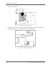
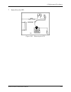
2. Remove the DC connector from its socket.
Figure 4-73 Removing the DC cable
4-60 Satellite A130/ A135 Series Maintenance Manual


