


2. ELECTRONICS SPECIFICATIONS EO18-33025
2.3 Description of the Main PC Board
2-7
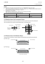
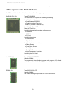
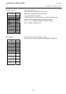
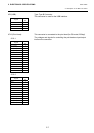
JP9 (USB): Type: Type B Connector
This connector is used for the USB interface.
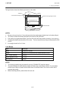
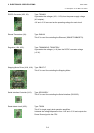
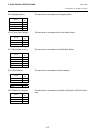
JP12 (Print Head): This connector is connected to the print head (for GS model, 203dpi).
The voltages and signals for controlling the print head are input/output
into/from the connector.
Signal
Pin
No.
+5 V 1
D- 2
D+ 3
N/C 4
GND 5
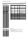
Signal
Pin
No.
VH (+24V) 1
VH (+24V) 2
VH (+24V) 3
VH (+24V) 4
GND 5
GND 6
/STB2 7
NC 8
TM 9
TM 10
VDD (+5V) 11
GND 12
/STB1 13
GND 14
JP12-1
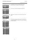
Signal
Pin
No.
CLK 1
GND 2
GND 3
GND 4
DI 5
/LAT 6
GND 7
GND 8
VH (+24V) 9
VH (+24V) 10
VH (+24V) 11
VH (+24V) 12
JP12-2