


2. ELECTRONICS SPECIFICATIONS EO18-33025
2.3 Description of the Main PC Board
2-8
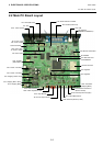
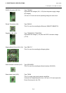
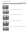
JP14 (Stepping Motor): This connector is connected to the Stepping Motor.
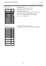
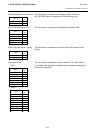
JP16 (Cover Open Sensor): This connector is connected to the Cover Open Sensor.
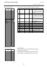
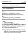
JP17 (Black Mark Sensor): This connector is connected to the Black Mark Sensor.
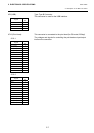
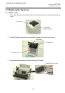
JP19 (Strip Module): This connector is connected to the Strip Module.
JP20 (Ribbon End Sensor): This connector is connected to the Ribbon End Sensor. (B-EV4T model
only)
Signal
Pin
No.
MB (PHASE1) 1
MA (PHASE1) 2
MB (PHASE2) 3
MA (PHASE2) 4
Signal
Pin
No.
+3.3V 1
HEAD 2
GND 3
Signal
Pin
No.
N.C. 1
+3.3V 2
BM_E 3
BM_R 4
+3.3V 5
Signal
Pin
No.
+3.3V 1
PEEL_SW 2
PEEL_E 3
PEEL_R 4
GND 5
Signal
Pin
No.
+3.3V 1
RIB_END 2
GND 3