


13
4. Installing The Interface
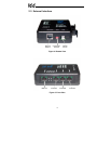
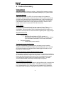
The ETH-100 connects to each drive via the drive’s common serial (logic level)
communication port, typically located on either the main drive control board
(G7), on the front of the drive enclosure under a small snap-on cover (A7, S9),
on the right-hand side of the drive enclosure under a small snap-on cover (S7),
or on the bottom side of the drive enclosure (VF-nC1). Although in general no
drive parameters need to be configured in order to use the gateway, it is
advantageous to check that the drive’s common serial communication data
rate is set to its maximum speed. Because the ETH-100 will communicate to
each drive only at the drive’s configured data rate, this will provide the fastest
response time for drive-to-network data transfers. For information on checking
the drive’s common serial communication data rate, refer to the appropriate
manual supplied with your drive.
Note that the common serial communication parameters of each drive are
handled independently by the ETH-100, which means that different drive
families may be connected to different channels of the unit in any combination,
and that the drives connected to each channel may simultaneously
communicate to the unit at completely different baud rates, parity settings, etc.
Drives can be connected to any ETH-100 channel in any order or combination.
When more than one drive is connected to the unit, the gateway will draw its
control power from the source with the highest power supply voltage.
Installation of the ETH-100 should only be performed by a qualified technician
familiar with the maintenance and operation of the connected drives. To install
the ETH-100, complete the steps outlined in the following sections related to
your specific drive.
4.1 Installation for G7 ASDs
1.
CAUTION!
Verify that all input power sources to the drives to
be connected have been turned OFF and are locked and tagged out.
2.
DANGER!
Wait at least 5 minutes for the drive’s
electrolytic capacitors to discharge before proceeding to the next step. Do
not touch any internal parts with power applied to the drive, or for at
least 5 minutes after power to the drive has been removed. A hazard
exists temporarily for electrical shock even if the source power has
been removed. Verify that the CHARGE LED has gone out before
continuing the installation process.
3. Attach the mounting clip and interface enclosure in your desired manner
(refer to page 12 for more information).