


32
12. Modbus TCP/IP
The ETH-100 interface supports Schneider Electric’s Modbus TCP/IP protocol,
release 1.0. The ETH-100 is conformance class 0 and partial class 1
compliant, and allows up to 8 simultaneous Modbus TCP/IP client connections
(sockets). Socket timeouts are set to 30s, which means that if a particular
open socket experiences no activity for more than 30s, then the interface
assumes that the client has experienced some sort of unexpected problem,
and the ETH-100 will close that socket.
12.1 Drive Channel Access
Each specific drive channel (Channel A, Channel B and Channel C) is
accessed via the “Unit Identifier” (UI) field of a Modbus TCP/IP packet. Drive
channel A is accessed when the UI field is set to “1”, channel B is accessed
when the UI field is set to “2”, and channel C is accessed when the UI field is
set to “3”. Any other UI setting is invalid and will result in a GATEWAY PATH
UNAVAILABLE exception (Modbus TCP/IP exception code 0A).
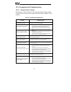
12.2 Supported Modbus Functions
The ETH-100 interface supports the Modbus TCP/IP function codes indicated
in Table 1.
Table 1: Supported Modbus TCP/IP Functions
Function Code Function
Class
3 Read multiple registers 0
6 Write single register 1
16 Write multiple registers 0
12.3 Modbus/Drive Register Mappings
The ETH-100 uses three methods to determine the manner in which Modbus
registers are mapped to ASD registers. These are outlined below.
12.3.1 Point Mapping
The unit can contain a user-configurable point database. The point database
is a list of register mappings that describe how Modbus holding registers map
to Toshiba ASD registers. Each point in the point database contains a
“primary network number” (know as pn number in this manual), a “secondary
network number” (know as sn number in this manual), a value, and a name.