


21
9. LED Indicators
The interface contains several different LED indicators, each of which conveys
important information about the status of the unit and connected networks.
These LEDs and their functions are summarized here.
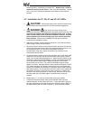
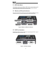
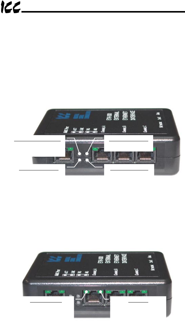
9.1 Module and Ethernet Indicators
The module and Ethernet indicators are located between the MMI port and the
Channel A drive port. Figure 6 indicates the functions of these LEDs.
MS (Module Status)
Currently reserved
NS (Network Status)
Currently reserved
LNK (Ethernet LiNK)
Solid green when valid
network link exists
ACT (Ethernet ACTivity)
Flashes red when network
activity is detected
Figure 6: Module and Ethernet Indicators
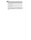
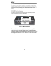
9.2 ASD Port Indicators
Each ASD port RJ45 connector contains two integrated green LEDs. Figure 7
indicates the functions of these LEDs.
Drive Link
Solid green when a logical
connection exists with the
attached drive
Network Access
Blinks in 0.1s-long bursts
when drive is accessed by
primary network master
Figure 7: ASD Port Indicators